Can someone please enlighten me about the addition of a large electrolytic capacitor to a High-Power 2-Channel 3W PAM8403 Audio Super Mini Digital Red Amplifier Board ?
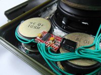
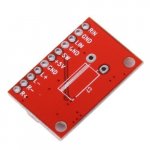
I came across an instructable to build a Bluetooth boombox and the design incorporates two High-Power 2-Channel 3W PAM8403 Audio Super Mini Digital Red Amplifier Boards. The instructable makes no mention of adding an electrolytic capacitor to the board but one is clearly visible in one of the pictures (shown - pic 1). Looking at the board (pic 2) it appears to have been added to C8 on the top side of the board. The underside of the board (pic 3) appears to illustrate solder points for an additional capacitor 'marked C7', but I can find nothing on the web to confirm this assumption, nor to clearly explain why the designer of the boombox has added one where he has.
Can someone please explain?
This is a link to the instructable:
DIY Tough Bluetooth Boombox (Lasts 20hrs!): 12 Steps (with Pictures)
Attachments

Any efficient audio Power amp needs a power storage reservoir. If it is "close" to the AC power supply that unit's filter cap can do the job. If there are long wires between, it is conventional to put some local storage "AT" the power amp.
> I can find nothing on the web to confirm
Try the spec-sheet. https://www.diodes.com/assets/Datasheets/PAM8403.pdf
> I can find nothing on the web to confirm
Try the spec-sheet. https://www.diodes.com/assets/Datasheets/PAM8403.pdf
Attachments
Lowering the LF impedance of the PSU improves the subjective bass quality. Works on pretty much all chipamps, classD or classAB.
I read about reducing EMI by putting a large capacitor at the power supply terminal, but the capacitor attached to the board in the picture didn't look to be that so I was confused.
Should I solder the cap to the back of the board where the line drawing is, or should I copy what the boombox designer did and solder it across C8?
Should I solder the cap to the back of the board where the line drawing is, or should I copy what the boombox designer did and solder it across C8?
Either will work, up to you. Just be sure and get the polarity correct unless you like the smell of freshly baked electrolytics [emoji6]I read about reducing EMI by putting a large capacitor at the power supply terminal, but the capacitor attached to the board in the picture didn't look to be that so I was confused.
Should I solder the cap to the back of the board where the line drawing is, or should I copy what the boombox designer did and solder it across C8?
Also wise [emoji23]LOL 🙂
Thanks. I'll avoid doing it half-cut!
The first picture is an example of wrong wiring/soldering skills.Wires should be put in the holes and then soldered.
BTW PAM8406 boards perform better and have slightly higher output power. This one even has output filtering and film caps at the input:
5wx2 stereo dual channel digital amplifier board pam8406 audio amplifier module 5v class d amplifier Sale - Banggood.com
IMO the PAM8406 sounds better than the PAM8403.
Last edited:
BS.Lowering the LF impedance of the PSU improves the subjective bass quality.
OBJECTIVELY (!) you get more and better boom. Boom-boom, you know?
Your guts will tell you the objective truth.
BTW PAM8406 boards perform better and have slightly higher output power. This one even has output filtering and film caps at the input😛AM8403.
Mmm OK. Anything which improves performance is worth serious consideration.
Does using the board you recommend negate the need for the extra 470uF cap? That would be another bonus.
🙂
Hi
No...if you look at the board you will find in the right corner 2 caps (silver with dark strip) with the label 470µF/16V. these are polymeer caps and these are good to stabilze the power on the rails.
chris
Mmm OK. Anything which improves performance is worth serious consideration.
Does using the board you recommend negate the need for the extra 470uF cap? That would be another bonus.
Hi
No...if you look at the board you will find in the right corner 2 caps (silver with dark strip) with the label 470µF/16V. these are polymeer caps and these are good to stabilze the power on the rails.
chris
That specific board has 2 x 470 uF polymer caps which really is enough. It also has a bead/coil for filtering in the power supply line. It is more thought out than the average PAM8403 board and it is still cheap/affordable.
Too bad it has a 3.5 mm jack connector for the inputs. I remove that connector and solder wires from the PCB solder pads straight to RCA connectors. Keep input wiring as short as possible!
Too bad it has a 3.5 mm jack connector for the inputs. I remove that connector and solder wires from the PCB solder pads straight to RCA connectors. Keep input wiring as short as possible!
Last edited:
Just for clarification purposes, you're claiming my experience is BS here?
That specific board has 2 x 470 uF polymer caps which really is enough. It also has a bead/coil for filtering in the power supply line. It is more thought out than the average PAM8403 board and it is still cheap/affordable.
Too bad it has a 3.5 mm jack connector for the inputs. I remove that connector and solder wires from the PCB solder pads straight to RCA connectors. Keep input wiring as short as possible!
Seems perfect! I'll use the board you recommend and do exactly as you suggest regarding the jack connector too. Many thanks 🙂
But .. is your experience objective or just subjective? Heh heh well.. is it from the epicentre of your intestinal tract or from you know, ... between your ears?Just for clarification purposes, you're claiming my experience is BS here?
One of those makes you go "wow, holy sh*t!"
BS.
OBJECTIVELY (!) you get more and better boom. Boom-boom, you know?
Your guts will tell you the objective truth.
Does 3W get you much Boom-boom?
Asking for a friend 😉
But .. is your experience objective or just subjective?
Would you answer my question, pretty please?
Hi JP
May i aks what you finally pay for the board and the deliver to your location?
chris
Hi Chris, I paid 6,58 Euro to seller ether.deal on Ebay.
- Home
- Amplifiers
- Chip Amps
- What is this additional capacitor added to PAM8403 Audio Amplifier Board for?