Have we settled on anything in this thread?
Again, I am confused as to why some people think that any change to the "signal" whether it follows a "RED LINE", Purple or Yellow w/ Pink Polka Dots is a "SIN".
Why not just stick the source RCA's into your ears and try to "HEAR" it unmolested!!!
A preamp (especially RIAA Phono) has INTENDED changes to the signal.
a) amplification
b) Equilization (according to the standard with is logarithmic ie NOT natural and not linear)
SO unless we were to use the exact same circuit used to encode the groove (in reverse) we will be changing the "signal" in playback!
I am not sure about everyone else but I would certainly rather "LISTEN" to my vinyl than TALK about it endlessly on the web.
It has been very interesting to see everybody's separate ideas on this subject. Maybe one day, somebody will come up with the idea of grounding the cathodes and introducing a grid bias battery. But then we will probably have arguments about the sonic performances of carbon, alkaline, Ni-Cad or Lithium batteries 😀
Oldeurope,
As someone said, I don't read German, even if I live in Schaffhausen. But I can read schematics and numbers, and guess at your points.
Anytime you want to compare my symetrical full preamp against ANY asymetrical preamp, yours or someone else's, I'm up for it. I don't care what numbers you may have calculated, it sounds better to me, and my clients for 25 years. We also make a near equivelent asymetrical version called the SVP-2. It also sounds good without any caathode bypass caps, but the symetrical one sounds better!
Regards, Allen
Originally #44 posted by Allen Wright
I'm with you, SY!
... check my website's schematics.
Regards, Allen
Hi Allen
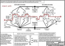
I did, I took one from your website and draw the signal path, see red line. 😉
OK, grid stoppers do not count.
Input --> FET 🙁 --> triode --> resistor --> cap --> triode --> resistor --> cap --> resistor --> triode --> triode --> cap --> Output
Tubes are welcome since this should be a tube based RIAA pre.
And the 'well known factor' is really bad. 🙁
Compare yours with the design in #9
LG Darius
Attachments
Darius,
> did, I took one from your website and draw the signal path, see red line.
OK, grid stoppers do not count.
Input --> FET --> triode --> resistor --> cap --> triode --> resistor --> cap --> resistor --> triode --> triode --> cap --> Output<
This has to be about the most basic and obvious thing one can do, but so what. It IGNORES the key factors that signal voltages are developed by CURRENT passing through paths to ground, such as the RIAA caps.
>Tubes are welcome since this should be a tube based RIAA pre<
OK.
>And the 'well known factor' is really bad<
I for one do not know what you mean by "the well known factor", hence I can't tell if it's bad or not.
But what about my listening test challenge? Or do you just play with red lines on screens?
Regards, Allen
Compare yours with the design in #9
<
You will not find the "well known factor" in world´s literature.
It is an invention of Darius himself.
And no, he is not interested in a challenge, his hobby is discussing schematics and tell that he can do better.
Reinhard
It is an invention of Darius himself.
And no, he is not interested in a challenge, his hobby is discussing schematics and tell that he can do better.
Reinhard
Allen Wright said:It IGNORES the key factors that signal voltages are developed by CURRENT passing through paths to ground...
As well as ignoring ground returns. The red line synopsis suggests sources will eventually run out of electrons.
Welcome back, Darius. Play nice, this time?
http://www.diyaudio.com/forums/showthread.php?s=&threadid=131810
http://www.diyaudio.com/forums/showthread.php?s=&threadid=131810
audiodesign said:C3 and G1 are on the signal loop
Yes, but agree, that from all known two-vacuum-tube schemes of amplifiers without IT, at my scheme the fewest (and, unfortunately, necessary) of intercrossed devices in transit a signal.
Especially devices with elements with minimal impact on the sound.
At transformer of supply of filament (at least my construction) extremely small impedance in the range of influencing sound.
At the accumulator also a small impedance.
And I apply capacitors only good to sounding):
An externally hosted image should be here but it was not working when we last tested it.
...
Sanyo Oscon... I am not very sure... are making quite a large grain in a difficult complex signal. But for digital audio i.e. for what they are intended by the development engineer, they unconditionally best, after BG with some letters.
@ #54
Hello Reinhard
I had a close look at ...
schematic
This is a RIAA in two steps. You need a buffer after the second filter. Note that the volume pot has an influence in the RIAA curve. If you want to use this thing as a stand alone RIAA pre, you need all components except the selector and maybe the pot. This is why I didn't gave the selector switch in my list #53.
Looks not good for Allen ... 😉
Darius
Originally #54 posted by reinhard
Have a close look, this one is a full feature preamp, not just Phono
Reinhard
Hello Reinhard
I had a close look at ...
schematic
This is a RIAA in two steps.
You need a buffer after the second filter. Note that the volume pot has an influence in the RIAA curve. If you want to use this thing as a stand alone RIAA pre, you need all components except the selector and maybe the pot. This is why I didn't gave the selector switch in my list #53. Looks not good for Allen ... 😉
Darius
Yes Darius, you are right, the pot is part of the RIAA. As a stand alone Phono you can add a CF after the 75uS/Neumann network.
Ok, the network needs some trimming.
As I know Allen is selling his Preamps very well, so it looks very good for him.
Discussing the schematic is not relevant for the customer, he can hear and decide if he likes the sound or not.
As you know, Allen and I are building preamps, the principles are different and we let the customer decide which one he likes better.
And at last: don´t think that you can tell Allen something new about preamp construction.
Regards,
Reinhard
reinhard said:And at last: don´t think that you can tell Allen something new about preamp construction.
[/B]
I would not be so assured...
Evaluating the designs of ... will be what to tell not only on preamp.
And a lot to say.))
Darius,
>his is a RIAA in two steps. You need a buffer after the second filter. Note that the volume pot has an influence in the RIAA curve. If you want to use this thing as a stand alone RIAA pre,
But why would you want to do that?
Yes, you would need a buffer after the 2nd filter, that is obvious, although if you factored in the capacitance of the interconnect cable, and the input impedance of the following "preamp", you don't need a buffer.
>Looks not good for Allen ... <
What looks not good for Allen, your writing is very hard to follow. And you are consistantly IGNORING my listening challenge! It's very easy to write stuff here, let's hear your stuff.
Regards, Allen (Vacuum State)
Definition debates come up regularly, over that of 'feedback' - local degeneration vs. loop - for example. The choice is usually less important than usage, which is where Darius makes no sense for me. What's the point in defining signal path in such a manner in which "Signal current causes voltage droppings and these are added (or subtracted) to the input signal between ground and grid" (bolding mine) and yet the component not be in the signal path? What extra explanatory power does this limitation grant the definition of 'signal path'? None that I can see.
Re: @ #74
Hi Darius,
The point I am making is that the signal path is an artificial construct, only perhaps useful for deciding where to put an oscilloscope or DVM probe. In all other respects it is of no interest to us at all, since the signal is manifested in almost every part of the circuit.
Alex
oldeurope said:
Hello Alex
please show me your way to draw the signal path into a schematic. (schematics e.g. #9 #53)
LG Darius
Hi Darius,
The point I am making is that the signal path is an artificial construct, only perhaps useful for deciding where to put an oscilloscope or DVM probe. In all other respects it is of no interest to us at all, since the signal is manifested in almost every part of the circuit.
Alex
@ #92
Hi Alex
I am a technician and for me and many others the signal path isn't an "artificial construct". I am happy that in good schematics the signal path is shown. There is no better way to show what's going on in a circuit.
If you want to sell a e.g. gold plated mains plug, it may be helpful to tell that signal path is "in almost every part of the circuit". Sad to see that you are not able or not willing to draw and follow the signal path. Maybe this #68 is the way you and your friends are thinking. I am sorry, I do not!
Darius
Alex M said:
Hi Darius,
The point I am making is that the signal path is an artificial construct, only perhaps useful for deciding where to put an oscilloscope or DVM probe. In all other respects it is of no interest to us at all, since the signal is manifested in almost every part of the circuit.
Alex
Hi Alex
I am a technician and for me and many others the signal path isn't an "artificial construct". I am happy that in good schematics the signal path is shown. There is no better way to show what's going on in a circuit.
If you want to sell a e.g. gold plated mains plug, it may be helpful to tell that signal path is "in almost every part of the circuit". Sad to see that you are not able or not willing to draw and follow the signal path. Maybe this #68 is the way you and your friends are thinking. I am sorry, I do not!
Darius
- Status
- Not open for further replies.
- Home
- Amplifiers
- Tubes / Valves
- What is the signal path -- the red line?