Wow, Darius sure knows how to win friends and influence people. 🙄
What is the signal path if not the flow of voltage and current?
What is the signal path if not the flow of voltage and current?
ashok said:I think SY and Conrad Hoffman have clarified that the audio signal does pass through all components that come in it's path including ones going to ground or any supply point. And strictly speaking all 'grounded' points are not the same or at "0.0000..." volts.
Why do you compare a coupling cap with a power supply cap ?
This European Triode Festival presentation goes a long way towards making it very clear that cathode caps & (at least) the last cap to ground in the power supply as VERY much in the signal path.
http://www.nutshellhifi.com/library/ETF.html
dave
coldcathode said:More gain at the expense of "minute" influences on signal integrity worth more than another stage have additional influences?
The issues is that the cathode bypass caps do not have a minute influence on the sound. They are a bit of a bottleneck.
However, there are ways around this including LED and or battery biasing, parafeeding with the return to the cathode instead of ground, connecting the cathode bypass to B+ rather than ground which may shorten the signal path and/or allow the use of a smaller and thus higher quality cap (there is some disagreement on whether or how this works), or using the resistance to one's advantage, though the last method makes transformer coupling difficult due to the high Zout of the stages.
coldcathode said:So question?
More gain at the expense of "minute" influences on signal integrity worth more than another stage have additional influences?
This should be a prime example of something we all know, or should have learned by now. There is no perfect circuit. Everything is a (hopefully) carefully chosen set of compromises. And I do mean everything. This is what's known as "designers choice". There are enough variables that everyone will never fully agree. Good or bad, right or wrong.
I understand what oldeurope means with his red line. Hewlett-Packard, the king of instruments, use it in their technical manuals. They even sub-divide it with solid and dashed lines for forward and feedback paths for clarafication purposes.
While some bypass capacitors (cathode/power supply) are not "directly" in the signal flow path, they are indirecly in it and must be included by proxy. It's actually a matter of how one was taught. But for the techicnal minded stickler, they're all in the path even if in a secondary or support function because they have influence and effect on the final end.
"Can't we all just get along?" LOL
No Rodney, food fights are fun. 😀
If anyone thinks that the cathode bypass capacitor is not in the signal path, then just take some cutters and snip them out... and then see what happens to your signal !!!
Remember: in reality there is no single track 'signal path'. That only exists on paper as a way to simplify understanding of circuit function. In real world application current travels in multiple interacting nodal loops.
And that includes cathode bypass capacitors.
Have a nice day.
Remember: in reality there is no single track 'signal path'. That only exists on paper as a way to simplify understanding of circuit function. In real world application current travels in multiple interacting nodal loops.
And that includes cathode bypass capacitors.
Have a nice day.
planet10
Strange... For some reason in your reference there is no my solution with a minimum crossing of sound currents plus fullpower work in regime A2 ...
Strange... For some reason in your reference there is no my solution with a minimum crossing of sound currents plus fullpower work in regime A2 ...
@ #5 and #32
Hi Vlauga
thanks for the link to your schematic, excellent. Your output is a “part three Loftin White” . I would recommend this for Andrea #1. A output loop is formed by C2, transformer and tube, the so called ultrapath. The cathode bypass is eliminated from the output current loop. 🙂 This is an advantage you can get from a transformer and Andrea should take it, shouldn't he?
Kind regards,
Darius
@ #30
Thanks HollowState
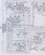
Yes, this is the usual way the signal path is drawn. In the attached schematic you can see the signal path for the left channel shown by little arrows. I can give you hundreds of examples from different manufacturers. I am surprised that so many forum members don't understand (or don't want to know) how to draw a signal path. If they don't get it from post #7, they'll never get it.
Kind regards,
Darius
Originally http://www.diyaudio.com/forums/showthread.php?postid=1746168#post1746168]#30[/URL] posted by HollowState
...
I understand what oldeurope means with his red line. Hewlett-Packard, the king of instruments, use it in their technical manuals. They even sub-divide it with solid and dashed lines for forward and feedback paths for clarafication purposes.
...
Thanks HollowState
Yes, this is the usual way the signal path is drawn. In the attached schematic you can see the signal path for the left channel shown by little arrows. I can give you hundreds of examples from different manufacturers. I am surprised that so many forum members don't understand (or don't want to know) how to draw a signal path. If they don't get it from post #7, they'll never get it.
Kind regards,
Darius
@ #36
Yes, but C3 gets “no” signal current from the output loop therefore no voltage drops at C3. The influence of C3 caused by the tube signal current in the signal is “eliminated”. 🙂
LG Darius
audiodesign said:C3 and G1 are on the signal loop
Yes, but
C3 gets “no” signal current from the output loop therefore no voltage drops at C3. The influence of C3 caused by the tube signal current in the signal is “eliminated”. 🙂LG Darius
Planet10 ..post 27 .
I didn't quite get what you mean. Did you think that I don't understand that the cathode bypass cap is in the signal path ? Or that supply caps also have signal currents passing through them ?
If you did then you misunderstood my post.
I did find in some preamp circuits the bypass cap degraded the sound. I'm not going to argue about this one. If anyone has doubts just pull out the bypass cap ( or use a different type and brand )and see if it affects your own circuit . In circuits with overall nfb it might behave differently. Pick what sounds best to your ears.
The bottom line is try it out on your own circuit build no matter what anyone else might say! Your evaluation of how it sounds is the correct one for your ears ! And that's all that really matters.
Cheers.
PS. If any component is connected to the 'signal path' and has a different voltage at its oposite end , it WILL bleed out current from the signal path making it a part of the 'signal path'.
@ #27
No, definitely not. The signal path shows the way from input to output, nothing more nothing less. The signal path and signal current loops are very different things. The signal path does not show signal current loops or measurable voltages above ground. The signal path is not a current loop. The following text quoted from the link above should be corrected. Urgent!
"Since it is easier to measure voltages than current, many engineers and audiophiles only think of the so-called "signal path" within an amplifier, where measurable voltages above ground appear. All the sloppy, hard-to-measure currents are usually ignored, especially currents that return along the ground path. But in reality, without current, there is no amplification, and certainly no power to drive a loudspeaker. And current, as you remember from grade school physics class, always requires a loop in order to flow and complete a circuit.
The true signal path in a functioning amplifier is a complete current loop that connects sender and receiver. The simplest possible amplifier has two separate current loops; one at the input, and one at the output."
Originally #27 posted by planet10
This European Triode Festival presentation goes a long way towards making it very clear that cathode caps & (at least) the last cap to ground in the power supply as VERY much in the signal path.
http://www.nutshellhifi.com/library/ETF.html
dave
No, definitely not. The signal path shows the way from input to output, nothing more nothing less. The signal path and signal current loops are very different things. The signal path does not show signal current loops or measurable voltages above ground. The signal path is not a current loop. The following text quoted from the link above should be corrected. Urgent!
"Since it is easier to measure voltages than current, many engineers and audiophiles only think of the so-called "signal path" within an amplifier, where measurable voltages above ground appear. All the sloppy, hard-to-measure currents are usually ignored, especially currents that return along the ground path. But in reality, without current, there is no amplification, and certainly no power to drive a loudspeaker. And current, as you remember from grade school physics class, always requires a loop in order to flow and complete a circuit.
The true signal path in a functioning amplifier is a complete current loop that connects sender and receiver. The simplest possible amplifier has two separate current loops; one at the input, and one at the output."
OK, so signal isn't voltage. Signal isn't current.

I suppose none of us are ready for the Mysteries of the Red Line.
I suppose none of us are ready for the Mysteries of the Red Line.
http://www.diyaudio.com/forums/showthread.php?postid=1746698#post1746698SY said:OK, so signal isn't voltage. Signal isn't current.
I suppose none of us are ready for the Mysteries of the Red Line.
Attachments
I'm with you, SY!
Never heard a good sounding red line in my life. And never heard a good sounding cathode cap either.
Phono can be done very differently, check my website's schematics.
Regards, Allen
Never heard a good sounding red line in my life. And never heard a good sounding cathode cap either.
Phono can be done very differently, check my website's schematics.
Regards, Allen
"Signal path", the red line, was used, I think, by Tek and HP and many others. It's extremely useful if you're a tech trying to fix something, especially if it's the first time you've seen that something. IMHO, most of the people here are very concerned with secondary influences and effects, so the concept of signal path isn't nearly as useful. Still, no points should be deducted for a well drawn schematic that includes a red line. 😀
Hi Allen,
Seconded, those RCA "red line" tubes just don´t cut it. 😉
Tom <ducking>
Never heard a good sounding red line in my life.
Seconded, those RCA "red line" tubes just don´t cut it. 😉
Tom <ducking>
Allen Wright said:I'm with you, SY!
...
Phono can be done very differently, check my website's schematics.
Regards, Allen
I checked your website ... read this one (german text):Die Symmetrie Falle
- Status
- Not open for further replies.
- Home
- Amplifiers
- Tubes / Valves
- What is the signal path -- the red line?