Hi,all,
As a beginner in HI-FI, I have very little knowledge about electronic circuits and I don't know what "Scheme feedback" means. Can someone explain it?
The following are some descriptions of pentades in triode mode,
a) Native triode mode
b) Series Schade mode on pentode
c) Reduced gain series Schade mode on pentode
d) Native triode mode with series Schedule mode added
Can someone explain the above differences with a simple circuit?
Thanks!
Triode mode (of a pentode or beam power tube):
Take a pentode or a beam power tube, and connect the plate to the screen grid (typically with a 100 Ohm resistor from plate to screen).
This amounts to 100% Local negative feedback from the plate to the screen grid.
Schade negative feedback.
http://rh-amps.blogspot.com/2013/02/rh84-amplifier-revision-2_26.html
Take note of the 100k Rfb resistor. It is output tube plate to driver plate negative feedback.
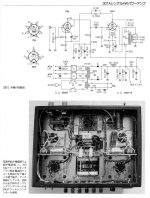
Maybe an interesting note: What folk on diyAudio are calling "Schade feedback" really isn't. O. H. Schade's famous 1930 paper describes an entirely different form of feedback, applied in series with the input signal rather than in parallel. At some recent point in time it was misunderstood, and the misunderstanding has become entrenched. See Fig. 33 for the original.
All good fortune,
Chris
All good fortune,
Chris
Attachments
Well, if one is interested in knowing things.Maybe an interesting note
I know that I am, that's why I'm here.
Pete
I'm not from here originally but I've been in Bethlehem Township the entire 21st century.Pete, you're from Bethlehem?
So far.
Pete
Chris Hornbeck,
Thanks for putting up the real Schade feedback document!
You really made me think about the two circuits, and the differences, so I wrote something up (attachment).
Your term, Entrenched is a good description of lots of words that are misunderstood.
Examples:
Tetrode used to be a true 4 element tube. A thoriated filament, a control grid, a screen grid, and a plate. 1, 2, 3, 4.
By the old definition, how are the KT66, KT77, and KT88 named Beam Tetrode?
filament, cathode, control grid, screen grid, beam formers, and plate. Even if you count the filament and cathode as one, they have 5 elements.
Tetra, from the Greek for 4, Not 5.
One more example:
A commonly used phase inverter, the LTP, has often been incorrectly described as a cathode follower stage, driving a grounded grid stage.
No, it should be called a cathode coupled phase inverter.
That is like describing an integrated assembly as a motor and a transmission; sure, describe it by its separate parts, but it is actually one item . . .
a Drive Train (or in many cases only a part of a drive train, depends on the total product).
Just my resistance to using old names to describe something that is new and different.
Attachments
Last edited:
Yes, and to the OP: series-connected negative feedback increases input impedance by the factor of (reduction of gain) and parallel-connected negative feedback reduces input impedance by the same factor. In the case of modern-term-"Schade" feedback output stage input impedance is impacted by the feedback resistor itself, divided by (gain of output stage + 1) as an additional load on the preceding driving stage.
Practically, the modern-term-"Schade" feedback puts the feedback loop at exactly the perfect place, but does so by heavily burdening the driving stage. All design is compromise.
All good fortune,
Chris
Practically, the modern-term-"Schade" feedback puts the feedback loop at exactly the perfect place, but does so by heavily burdening the driving stage. All design is compromise.
All good fortune,
Chris
This was discussed some time ago here . THe "stage local" feedback term was used for a while after that. Surprising that Schade's name is back as "Stage Local" sounds so much cooler, like we know what we are doing. : )
Seems like there was a lot of confusion of terms even back then, and it's only gotten worse. Stage Local or Anode Follower would at least be correct. Thanks.
All good fortune,
Chris
ps: Some will argue with Anode Follower, but that's what C. P. Boegli called it in about 1961, so it has some history.
All good fortune,
Chris
ps: Some will argue with Anode Follower, but that's what C. P. Boegli called it in about 1961, so it has some history.
merlin el mago,
I am not sure what you are asking.
For a real Schade amplifier:
Start with fig. 33 on page 41 that was provided by Chris Hornbeck.
Re-calculate the resistances, output transformer, B+, etc. to use the 307A at optimum operating conditions.
It is push pull. You will have to do modifications to use it for single ended.
For the modern misuse of the Schade name:
I you want a schematic so you can use a 307A for a Schade negative feedback amplifier, start with the RH84 schematic.
You will need to adjust resistor values, output transformer, B+, etc. as appropriate for optimal operating conditions.
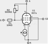
To make the amplifier as much like the RH84, you need to connect the 307A suppressor grid to one end of the filament (right at the 5 pin socket).
I would call the 307A a True 5-element Pentode (it does not even have a dual element filament/cathode combination).
DHP, Direct Heated Pentode? How about that for a 3 letter acronym.
Have fun!
Last edited:
Merlin,
It looks like you have spent more time with the 307a than at least most if not all others here who have tried it. What circuits have you tried with it and where do you want to take it now? Get more power out of it? Run it as a pentode ?
It looks like you have spent more time with the 307a than at least most if not all others here who have tried it. What circuits have you tried with it and where do you want to take it now? Get more power out of it? Run it as a pentode ?
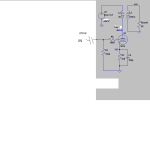
Thanks for answers guys, I want to use it for a headphone amp. Original schematic posted by ikoflexer, still not tested. OPT Edcor 15K-600R 5W gapped. I think no Schade used.
Attachments
Last edited:
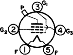
I'm not tried nothing because I don't know how to connect G1, G2 & G3, also I want to use it in horizontal plane not vertical but not sure the proper orientation of filaments: for sure horizontal but I don't know if up or down (attached pinout shows horizontal down)?
That's and not knowing the correct Schade SE schematic left the project on stand by.
That's and not knowing the correct Schade SE schematic left the project on stand by.
Attachments
Last edited:
As others have stated, O. H. Schade used series-applied voltage feedback in his 6L6 paper. He did it through an arrangement with an interstage transformer and resistors. The reason he did that was because he wanted to plot curves with different amounts of feedback for the paper he was writing and he could do that by just swapping out resistors. For whatever reason, he stayed away from parallel-applied feedback. He might not have wanted to mess with the low input impedance. His goal with his circuit was to produce some plots to help convince people to purchase 6L6s.
For some reason, it has become popular here to refer to parallel-applied voltage feedback around a singe stage as "Schade" feedback. Schade didn't invent single stage feedback, nor is this the kind of feedback he used in his paper.
Of course, the simplest way to get single stage series-applied voltage feedback around the output stage is to use a cathode feedback winding. This is more similar to what O. H. Schade did in his paper, but you can't just change the amount of feedback by swapping some resistors, and you also have to make screen voltage track cathode voltage or you will have some UL feedback on the screen due to the cathode swing. Some people consider the free UL feedback to be a benefit but I do not.
Last edited:
Curious why you add the word "applied". Is it just the way you like to think of it or is it a term indicating something different? I'm not (yet) very knowledgeable about feedback so I have to ask. Thanks
- Home
- Amplifiers
- Tubes / Valves
- What is the "Schade"


