http://pro-radio.ru/user/uploads/11566.pdf
please scroll till the end of the acrobat doc..
is it required? if so the parts make difference to which stage in specific? VAS or output stage? and what is the role of these R4 and D1
please scroll till the end of the acrobat doc..
is it required? if so the parts make difference to which stage in specific? VAS or output stage? and what is the role of these R4 and D1
They are both a part of power supply.
D1 rectifies the power.
After this R4 and C1 will smooth the power line.
R4 and C1 will form a RC-filter to make very clean power to the input of amplifier.
So, R4 and D1 are important parts of power supply rail.
D1 rectifies the power.
After this R4 and C1 will smooth the power line.
R4 and C1 will form a RC-filter to make very clean power to the input of amplifier.
So, R4 and D1 are important parts of power supply rail.
R4 and C1 along with R57 and C26 on the negative side decouple (isolate) the front end from the output stage. D1 and D2 prevent the output stage from stealing voltage from the front end when the power supply voltage drops in the output stage during heavy loads.
Craig
Craig
what if we have isolated psu for vas and output stage? then at that time there will not be any necessity of using these isnt it?
I'm sure that would work but you are trading 10 cents worth of parts for what gains. These are for PA use?
Craig
Craig
yeah preferably for PA use...
but I have a question on power amplification calculations...
like for a psu of 90v the power in load be calculated in with losses of may be 11% p = v^2 / R so here its
6400 x 8 = 800w but the power ratings are rated as 450watts in 8 ohms... Im just doubtful on my calculations can anybody correct me in these psu calculations..
Your calculation math is fine but there are far more losses than what you calculated 🙁
Copper and iron PSUs drop around 20% if lightly loaded (as into 8 ohm loads) and around 30% if into 4 ohm loads (that's why 4 ohm power is not 2X 8 ohm power but only around 50% more)
You also lose about 4V per output transistor, 2 more per driver, 2 more for either the Vas or the CC one at the other end.
You also lose 2 to 3V per emitter ballast resistor.
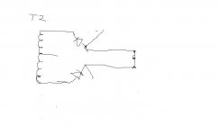
My question is about the lower (stereo) power supply schematic. In all previous forum threads it's mentioned repeatedly that a center tapped transformer can only be connected to a single bridge,and here we have an example of a dual bridge with CT. I understand that this is a 'floating earth'. But why the aversion to this setup? Is there a disadvantage in using it?
Cheers
Cheers
My question is about the lower (stereo) power supply schematic. In all previous forum threads it's mentioned repeatedly that a center tapped transformer can only be connected to a single bridge,and here we have an example of a dual bridge with CT. I understand that this is a 'floating earth'. But why the aversion to this setup? Is there a disadvantage in using it?
Cheers
Actually - Good catch. Shouldn't work as posted. Relevant part with bad art. Two diodes in same orientation across transformer will not fly.
Attachments
Last edited:
Hi Steve,
Is there a way to make it fly with the two bridges?
If so,could you draw it please?
Thanks
Is there a way to make it fly with the two bridges?
If so,could you draw it please?
Thanks
If the transformer had 2 separate/unconnected windings, each one with its own bridge would feed one rail.
But as is it does not work.
Why do you *want* to use 2 bridges?
But as is it does not work.
Why do you *want* to use 2 bridges?
If it wasn't there you would get hum on low listening levels.
There is sometimes a resistor and capacitor that do the same job.
Its basically a little decoupling. Decoupling output stage from input stage.
There is sometimes a resistor and capacitor that do the same job.
Its basically a little decoupling. Decoupling output stage from input stage.
Hi Steve,
Is there a way to make it fly with the two bridges?
If so,could you draw it please?
Thanks
😱 If I knew a way I'd be famous - but I haven't. It's kinda like the 4 color map thing - after fiddling with it you become convinced that its true, but proving it is another can of worms (FWIW eventually proved with computers)
- Status
- Not open for further replies.
- Home
- Amplifiers
- Solid State
- what is the role of R4 and D1 in the schematic