
They protect the output devices from inductive loads, by clamping the output node to the rails.

If the output is ever FORCED by the speaker to exceed the rail voltages it will clamp it there so it doesn’t destroy the output transistors. An abrupt decrease in current while the load is inductive will do this. It can happen if it goes into current limiting or if the signal is suddenly removed.
Thanks rayma sir..They protect the output devices from inductive loads, by clamping the output node to the rails.
Thanks wg-ski for explanation..If the output is ever FORCED by the speaker to exceed the rail voltages it will clamp it there so it doesn’t destroy the output transistors. An abrupt decrease in current while the load is inductive will do this. It can happen if it goes into current limiting or if the signal is suddenly removed.
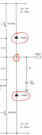
Note that the schematic diagram is incorrect and may be why you are having a problem understanding the diodes' function. There should be a junction (shown as a small dot) at the point where the diode leads cross over the output lead, like the other dots shown. Otherwise, they won't do anything useful.
Last edited:
Always good to have protection from inductive kickback.
High power amps with current limit or any output section with current limit
they should be considered a necessity
the initial inductive kickback spike can be very quick and short.
but the voltage can often be twice the rail voltage or more.
so the transistor voltage can be exceeded
many or most general purpose Darlington packages intended for switching applications
can have the diode included in the transistor itself
Thanks man and I know there is a junction point that is not shown properly in schematic..Note that the schematic diagram is incorrect and may be why you are having a problem understanding the diodes' function. There should be a junction (shown as a small dot) at the point where the diode leads cross over the output lead, like the other dots shown. Otherwise, they won't do anything useful.
You are right as u said these diodes won't do any thing useful..
Now i have come to know all about the topology of these diodes..Always good to have protection from inductive kickback.
High power amps with current limit or any output section with current limit
they should be considered a necessity
the initial inductive kickback spike can be very quick and short.
but the voltage can often be twice the rail voltage or more.
so the transistor voltage can be exceeded
many or most general purpose Darlington packages intended for switching applications
can have the diode included in the transistor itself
View attachment 1036388
And very good and deep explanation sir you always helped me a lot many thanks for you

Sorry but no, look again: diodes go from speaker out HOT to positive and negative rails.Helo friends it is simple but very complicated l just want to know that what is the purpose of these diodes in amplifier from negative to ground or positive to ground. or what are benefits by using this toplology??
Thanks..
Ground is irrelevant here.
Last edited:
Its also a wise precaution to have similar diodes between the rails and ground, so that if one power rail goes down it can't be forced to the wrong polarity (although more sophisticated supply-rail monitoring protection circuitry is often part of amp designs).
Its worse than that.the initial inductive kickback spike can be very quick and short.
but the voltage can often be twice the rail voltage or more.
so the transistor voltage can be exceeded
When the inductive spike happens, the emitter voltage exceeds the collector, which is BACKWARDS. Transistors really don’t like that. The amount of breakdown energy they can absorb in that mode is far less than what they can take if you just exceed Vceo.
One of the designers from Mark Levinson / Harman International answered the question here on the Forum a few years ago, rather hilariously.
Those diodes protect the amplifier from self destruction when (a) it's playing at a demonstration or audio show; and also (b) it's playing loud, and also (c) some idiot trips over a speaker cable, thus disconnecting the amp from its complex load when output current is high.
D. Self's power amp book recommends the 1N540x series (3 ampere rated) diodes in these positions.
That's not what he said.You are right as u said these diodes won't do any thing useful..
Jan
Ohh sorry sorry JMFahey sir you are absolutely 100% right when I saw the schematic of nap 140 I realized that I was wrong yes the diodes go from speaker out HOT to positive and negative rails..Sorry but no, look again: diodes go from speaker out HOT to positive and negative rails.
Ground is irrelevant here.
Or ground is irrelevant here...
See this is right schematic.
Attachments
- Home
- Amplifiers
- Solid State
- What is the purpose of these diodes???