Hello All,
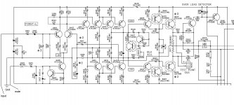
Here is the schematic of my power amplifier. Its highs are not crisp rather dull, bass is not tight and vocals are muddled. Can any body tell me what is the problem with this amp? And how can I mod this amp to get crisp highs, tight bass and clear vocal?
Thanks,
Nageswar😎
Here is the schematic of my power amplifier. Its highs are not crisp rather dull, bass is not tight and vocals are muddled. Can any body tell me what is the problem with this amp? And how can I mod this amp to get crisp highs, tight bass and clear vocal?
Thanks,
Nageswar😎
Attachments
Hi Nageswar,
Is this your design? Neat looking…
At first glance it looks like you’re using current mirrors as the VAS. Interesting way of using a single diff. and a class AB VAS stage. It appears that the bias is set by the current source of the differential. However every mirror is like another stage in slack time. The time it takes to turn on a transistor and turn it off adds delay which can cause some dulled highs when inside the feedback loop because of the compensation needed to keep from oscillating. How about a current mirror in differential stage? Might compensate better. You would need to add emitter diodes to Q411 & 413 though. Just some suggestions but it seems like there is always trade offs to anything you do.
Is there a reason for using two sets of VAS transistors instead of 1 larger one? What is the reason you use class ab VAS & mirrors instead of class A w/current source? Trade offs?
Interesting cutoff circuit.😎
Is this your design? Neat looking…
At first glance it looks like you’re using current mirrors as the VAS. Interesting way of using a single diff. and a class AB VAS stage. It appears that the bias is set by the current source of the differential. However every mirror is like another stage in slack time. The time it takes to turn on a transistor and turn it off adds delay which can cause some dulled highs when inside the feedback loop because of the compensation needed to keep from oscillating.
How about a current mirror in differential stage? Might compensate better. You would need to add emitter diodes to Q411 & 413 though. Just some suggestions but it seems like there is always trade offs to anything you do. Is there a reason for using two sets of VAS transistors instead of 1 larger one? What is the reason you use class ab VAS & mirrors instead of class A w/current source? Trade offs?
Interesting cutoff circuit.😎
Hi Nageswar,
Okay, it's a Korean schematic and / or design. Confirm the tail current is high enough for starters. Same for the vas input transistors.
-Chris
Okay, it's a Korean schematic and / or design. Confirm the tail current is high enough for starters. Same for the vas input transistors.
-Chris
routhun said:
Here is the schematic of my power amplifier. Its highs are not crisp rather dull, bass is not tight and vocals are muddled. Can any body tell me what is the problem with this amp? And how can I mod this amp to get crisp highs, tight bass and clear vocal?
I see four areas that might be dealt with:
1) The zobel between the collectors of the LTP.
2) The two capacitors C409 and C411.
3) The unnecessary VAS dual transistor.
4) The capacitor bypassing R469, which IMHO might be smaller and a film type.
Carlos
Hi CBS240,
This is not my design, it is the schematic of the power amplifier of my Harman Kardon AVR520 receiver. When I compare the sound of this receiver with my Nikko NR-1019 receiver I found the sound from AVR-520 is rather dull. Initially I suspected the preamp in this receiver, so I drove this amp from the Nikko's main out. There was a little improvement, so I thought of modding this amp could bring its sound to comparable to Nikko. I could not think of any mods of my self so I posted on this forum. I don't know why they choose certain configuration like dual VAS transistors and other tradeoffs. But I would like to start with simple mods as suggested by carlos, and move to complex mods suggested by you. Carlos can you suggest me what would be the best value for C415 (the capacitor bypassing R469) and values for Zobel network between collectors of LTP and capacitors C409 and C411?
Thanks,
Nageswar
Hi Nageswar,
I sold an NR-1019 to a friend years ago, he still has it. A really nice sounding rcvr from years gone by.
-Chris
I sold an NR-1019 to a friend years ago, he still has it. A really nice sounding rcvr from years gone by.
-Chris
I was being very general in assuming that this is a design in progress. Not to say that it can't be improved, obviously. But this is where you might get into the 'design you own' mode....best way to learn though.
Hi CBS240,
Sorry for the confusion that I caused. I am not sure whether I can post a copy righted schematic on this forum, but I want to mod this amp, that's why I didn't say it is the schematic of my harman kardon receiver in my first post. But after lot of questions about the design I need to reveal its source.
Thanks,
Nageswar
Hi Chris,
The Nikko receiver was given to me by somebody with left channel out. I replaced the outputs with MJL4281A and MJL4302A complementary pair. After replacing the outputs sometimes outputs on that channel is used to get very hot. After some more checking I found that capacitor in the output Zobel network is open. I replaced that and it is working fine from then.
Bass is really tight from this receiver. I really like the sound. The real good part in this receiver is its tuner section.
Regarding AVR-520 receiver, the preamp of this receiver contains lot of opamp buffer sections with lot of compensating capacitors and mute transistors in the signal path. With all this heavy handed signal processing I think quality was deeply buried in the preamp itself. I am thinking of repeating my test with Nikko preamp and Harman's power amp section and I'll post the result.
Thanks,
Nageswar
Hi Nageswar,
That should be an interesting experiment. Later Nikko's did not sound very good sadly.
Do you have a schematic for the NR-1019? I may be called upon to repair my friends unit any time now. It is very old and I've cleaned the switches once for him.
-Chris
That should be an interesting experiment. Later Nikko's did not sound very good sadly.
Do you have a schematic for the NR-1019? I may be called upon to repair my friends unit any time now. It is very old and I've cleaned the switches once for him.
-Chris
Hi Chris,
I don't have the full schematic of the Nikko receiver, but I hand traced the schematic of the power amp section. If you want that, I can scan and mail it to you.
Thanks,
Nageswara
I don't have the full schematic of the Nikko receiver, but I hand traced the schematic of the power amp section. If you want that, I can scan and mail it to you.
Thanks,
Nageswara
Hi Nageswar,
That's very kind, thank you! If I come across the manual I'll get you the full schematic. Send it to bhome at sympatico dot ca. My profile link works too.
-Chris
That's very kind, thank you! If I come across the manual I'll get you the full schematic. Send it to bhome at sympatico dot ca. My profile link works too.
-Chris
Some good suggestions here, I'd lose the lytic in the input after the 330R, replace with a metalized poly, or PIO.
I have been studying amplifiers for decades (4) and i could not see nothing that can
Produce the sound you are perceiving.
Well, lets see if i will have time enougth to learn more, because this is showing me that i need to construct more, listen more to have more experienced looking schematics.
Sorry my question.... had you compare them only with power amplifiers operating....no pré amplifier, filter or processors in the chain?.... sorry, i really think you made your tests with a power in separated mode.
Those small transistors in parallel are to face the power needed in that stage, dividing power and using the hi gain characteristic of those transistors...one single hi power unit will loss in gain.
I could not find nothing to replace...nothing to change, and my imagination showed me a nice sounding amplifier.
regards,
Carlos
Hi Carlos,
You are right, this is a nice sounding amplifier. I've built a preamplifier using an opAmp and bypassed the pre-amp in this receiver. It sounded very well. So I went on searching for an used preamplifier for this receiver. Finally I got hold of Yamaha C-4 preamplifier. The sound from this Yamaha C-4 and Harman Kardon AVR-520 combination is phenomenal. Guys if you want a discrete line amplifer, discrete class A headphone amplifier, and an optional two band parametric equalizer - look no further all these qualities are in Yamaha C-4. Its a fully discrete preamplifer with matched JFETs in input stage. It transformed my audio experience.
Thanks,
Nageswar
- Status
- Not open for further replies.
- Home
- Amplifiers
- Solid State
- What is the problem with this amp? mods requested