I have a pair of output transformers on a stereo 845 SET amp and I question whether they are wound correctly. I measured their turns ratio and found the 8R taps to be 26:1. The 4R are 36.6:1. For those without calculators within reach, that works out to about 5K4. That doesn't seem like the correct choice to me.
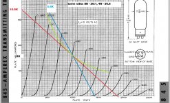
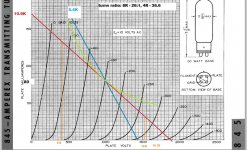
The attached file is plate characteristic curves drawn with an 80ma OP at 1000v which represents the amps design. The BLUE line represents the transformer loaded as speced. The RED line is a 10.9K load; the transformer's 4R taps connected to an 8R load (or the 8R taps connected to a 16R load).
If I have this thing drawn correctly, it seems to me that this amp would best be operated with the doubled loads to follow the red curve. This conclusion would mean that the manufacturer screwed up the transfo design on a production amp. An equally probable conclusion would be that I have a misunderstanding of the of the plate characteristics.
Please have a look and tell me what you think.
Attachments
http://tubedata.milbert.com/sheets/111/8/845.pdf
According to the above 9K is recommended, so your calculations seem right on. The Manufacturer probably used 5Kwhatever as a cost saving measure.
The 845 will work well with the Manufacturer's transformer, but with a 10K load the distortion will be less, damping facter higher so it will probably sound better. Triodes arent that critical with load presented to them, but there will be an optimum operating point, which 10K seems to be more so than 5K.
Daniel
Of course, connecting a 16 ohm speaker to the 8 ohm tap of your transformer will effectively double the primary impedence, but then the primary inductance of the transformer will be too low for corresponding impedence of the primary, so low frequency response of the transformer will suffer.
Last edited:
Depends on the application. For example, at about 750V plate voltage and class A1 operation 5-6K is a very good choice. You get about 12W with low THD.
10K is better for high voltage. However a 10K OPT for such application is a lot more difficult to make in comparison to 5K. If the transformer is a standard type (and even more if cheap) a 5K OPT is typically a better performer than a 10K OPT of the same quality
10K is better for high voltage. However a 10K OPT for such application is a lot more difficult to make in comparison to 5K. If the transformer is a standard type (and even more if cheap) a 5K OPT is typically a better performer than a 10K OPT of the same quality
Anyway you should get about 24W at 5% THD from the load line at 1000V 80mA which is not bad at all! Driving the 845 into class A2, even for few volts, is quite challenging....
Last edited:
The 'traditional' load for a power triode is 2*ra, plus a little bit to reduce distortion perhaps, so 5.4k is a perfectly reasonable choice. It doesn't matter that the load line goes over the dissipation curve for part of its length, since the average power is roughly constant, and is determined by the bias point. Notice that with the 5.4k load the bias point is almost dead centre, which looks deliberate to me. You might prefer a larger load to reduce distortion more, at the expense of some output power, but they certainly didn't screw up the design.
Last edited:
Thanks everyone.
Merlinb, I'm very glad to hear you weigh in for the design. I posted hoping to hear that the tranfos are just fine and that my understanding is to blame. But, I don't completely follow you. Can you please elaborate on these two questions?
I didn't know that 2*ra is a traditional load for a triode. I can see that ra is about 2K and so it follows that 5.4K could be a very reasonable choice. So, I went back to the Amperex data sheet and noted that they show values for load resistance of 3K4 @ 750v, 9K @ 1000v and 16k @ 1250v. But ra is virtually unchanged at these three OPs. What IS changing is the max power dissipation curve. I think I read in Morgan Jones (or somewhere) that the load line (for a small signal triode) should be tangent to the dissipation curve which is more in line with the specs I just sited. Those two criteria seem quite at odds with one another. (What is it they say about a little understanding?)
I get that the load line can exceed the dissipation curve for half of its cycle, but I don't really see that the 5.4k line is dead center any more than is the 10.9k. I suppose I'm asking, dead center of what?
Thanks for your help.
Last edited:
........Please have a look and tell me what you think....
My method to determine which output give best performance would be to measure the frequency response, max. output power and THD, also at the low bass frequencies.
Playing with the load line is just theory and can lead to an incorrect result.
And of course listening is important.
Playing with the load line is just theory and can lead to an incorrect result.
It's difficult to design the driver stage without selecting a load line. The 10.9K line is much more difficult to drive than the 5.4K line. And perhaps that is the reason for the 5.4K windings.
This is one view to the design procedure, but now the case is a bit different.
You have an existing amplifier with existing output transformer and two possible ways to connect it.
Which one is better (objectively) is simply determined with the measurements.
Usually driver stages should be designed by looking at the loadline but in addition with plenty of headroom.
The driver stage can also be analyzed with suitable measurements.
You have an existing amplifier with existing output transformer and two possible ways to connect it.
Which one is better (objectively) is simply determined with the measurements.
Yes, I understand your point now. The driver stage in this amp is not a good one and will need to be redone before I can make any measurements. I'll post on that soon but for now I don't want to threadjack my own thread.
Driving the 845 into class A2, even for few volts, is quite challenging....
Yes indeed. Do you have any idea where the onset to A2 would begin? I'm thinking of a 240v swing, so I'd be driving it to about -30.
That should be good for almost 32 watts.
Attachments
Last edited:
2*ra is the condition that results in maximum power transfer, among some other useful rules of thumb; you can find this in any tube textbook (maybe not Jones?).I didn't know that 2*ra is a traditional load for a triode.
Magic Thirds and 2rp
That is a conservative rule to prevent the anode dissipation from ever exceeding the max. But what really counts in the average dissipation, so you can break this rule a little, if you're careful.I think I read in Morgan Jones (or somewhere) that the load line (for a small signal triode) should be tangent to the dissipation curve which is more in line with the specs I just cited.
Yes indeed. Do you have any idea where the onset to A2 would begin? I'm thinking of a 240v swing, so I'd be driving it to about -30.
That should be good for almost 32 watts.
At -30V you are well within class A1. Typically grid current starts around -5V (average). Anyway you won't get 32W from the 10.9K load-line and 240V p-p swing. The Pout will be 14W but THD is only about 1.5%.
As I told before you can get the same Pout with 5.4K OPT with less plate voltage, less plate dissipation and the same swing.
With such OPT I would try something like 850V/80 mA to get a Pmax around 20-21W without (formally) going into positive grid. At 14W THD will be quite low anyway. You need about 240-250V p-p and a little bit of power drive. DC coupled cathode follower will do fine.
The power transformer that came with this amp has two B+ windings and produces a B+ of 1000vdc and about 420vdc for the driver stage. It would dissipate about 24 watts of heat dropping the B+ to 850. It's not out of the question but you can see how i'd like to stay with the 1000v B+.
But I must not be calculating Pout correctly. On the 10.9K load line I posted in #12, the 240v swing (from -30 to -270) results in a anode swing from 1530 to 410 = 1120vpp. So, according to my math, 1120vpp*80ma/(2*sqrt2)=31.7w. Is that not right?
But I must not be calculating Pout correctly. On the 10.9K load line I posted in #12, the 240v swing (from -30 to -270) results in a anode swing from 1530 to 410 = 1120vpp. So, according to my math, 1120vpp*80ma/(2*sqrt2)=31.7w. Is that not right?
Merlinb, thanks for that link. That's very useful. I recall reading that long ago, but I guess the relevant parts didn't take🙂
I'll rethink the design in light of that article. I can see 45's point that I have too much B+.
I'll rethink the design in light of that article. I can see 45's point that I have too much B+.
Last edited:
If you connect the 8ohm speakers to the 4 ohm secondary, u will get the 10k primary impedance, but of course your inductance will be lower than a true 10k OPT
But I must not be calculating Pout correctly. On the 10.9K load line I posted in #12, the 240v swing (from -30 to -270) results in a anode swing from 1530 to 410 = 1120vpp. So, according to my math, 1120vpp*80ma/(2*sqrt2)=31.7w. Is that not right?
That is not correct. Do not use the quiescent current ( 80 mA) in this calculation. It is the signal current that generates the output power.
You have 1120 Vpp swing across the 10.9k load.
P = UxU/R
1120 Vpp/2,83 = 396 Vrms
Pout = 396 V x 396 V / 10.9k = 14.4 W
- Status
- Not open for further replies.
- Home
- Amplifiers
- Tubes / Valves
- What is the correct load for an 845 triode?