Hello,
could you guys please tell me the recommended/best way to wire a bias trim-poti for a KT88 / KT120 PP amp ?
It seems to me the version A in the attachment is more reliable and the version B has a constant RC, but I do not really know if I should trust the PNP ? I know about the problem with the wiper of the potis.
Any suggestions for a better schematic are welcome.
Attachments
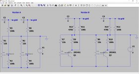
Version 'B' suffers from the problem if the wiper of the pot goes O/C then the grids will get 0V which is very bad.
Careful with the polarity on the bias supply. You want to apply a negative voltage to the power tube grids.
Make the tradeoffs:
A little less power output.
Lots more reliable.
No adjustment needed with good tubes, they need not be professionally matched.
. . . Plug and Play.
How?
Eliminate potentiometers.
Eliminate PNPs.
Eliminate Negative Bias Supplies.
Sound to good to be true?
Use Individual Self Bias Resistors, that are Individually Bypassed with Capacitors.
Do not use adjustable fixed bias.
A simple method with only 3 resistors and 2 caps, is individually self biased for DC balance, but it also provides cathode to cathode coupling for AC balance.
Ask me, if you are curious (I learned it on this forum).
Last edited:
Make the tradeoffs:
Ask me, if you are curious (I learned it on this forum).
Of course I am very interested ! I ask/beg you on my knees, please show me a schematic and tell me everything 😀
Have a read of fixed bias and self bias on the internet.
Self bias means the bias is generated between the cathode and ground of the output device and the grid is set to 0V. This negative feedback means its self regulating and self protecting, and does not need a negative supply - easy to implement.
However you loose some output power as this reduces the swing, you throw a few watts at the cathode resistor. The biggest problem I have with it is that if you are push-pull when you get to large signals in class 'B' the current in each half goes up causing the cap to charge up more and the bias drops to the extent of introducing crossover distortion.
You did not say whether your amp is SE or PP.
Fixed bias puts the cathode at 0v and biases the grid negative. You get full output swing and no change in bias point with output level. However the bias has to be set manually for the valve by measuring cathode current. The bias needs to be supplied via lower resistors in case the grid current starts to go up into thermal runaway. This can impact on driver swing. If the negative supply fails you can damage the valves and the OPT. Test with valves removed to check the negative voltage is present on the grid pin. The negative bias should be smoothed so it does not modulate with the signal on the grids.
Small amps - self bias, Big amps - fixed bias.
There is also servo bias. You buy a PCB in that controls the grid voltage by measuring cathode current. These can be retro fitted to fixed bias amps.
Hope that's an unbiased opinion.
Last edited:
In Class A1 push pull, both the average current of "Push" and the average current of "Pull" stays relatively constant.
In Class AB1, when it leaves Class A1, it goes to Class B1.
While in Class B1, the current in "Push" increases (but only for 1/2 of the time: the rest of the time is divided between Class A1, and complete cut off almost 1/2 of the time).
While in Class B1, the current in "Pull" increases (but only for 1/2 of the time: the rest of the time is divided between Class A1, and complete cut off almost 1/2 of the time).
With all the time that is spent in cutoff, the Average current does not go up quite as much as you might expect.
So, When in Class AB1, the Average current in Push and Average current in Pull stays
somewhat the same.
I think this latter point escapes many peoples understanding.
Now if you are talking about Class B, that is another story.
I do not ever use Class B in any of my amplifiers, so I will defer to others to talk about Class B.
Thank You "Class B" fans!
Now if you are talking about Class AB2, that is another story.
I do not ever use Class AB2 in any of my amplifiers, so I will defer to others to talk about Class AB2.
Thank You "Class AB2" fans!
Last edited:
Sorry when I say 'B' I mean the class 'B' section of class 'AB' I don't mean true class 'B'. I mean one valve cut off. If you use cathode bias you run the valves at nearly full plate dissipation (for a EL34 amp) for the push to be similar to the pull or you get into crossover distortion at high loads. I found this does happen if you drive full sinewave. If you run fixed bias you can run the bias at a lower value which helps with valve lifetime. I am not discussing AB2 either it needs a different driver often. You can replace some of the cathode resistor with a zener which gives you a better compromise I think.
Last edited:
alujoe2,
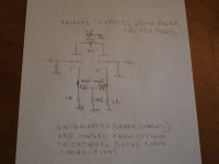
I am attaching the schematic of self bias that corrects for un-balanced signal errors.
This applies to Push Pull amplifiers; it does not apply to single ended amplifiers.
I am attaching the schematic of self bias that corrects for un-balanced signal errors.
This applies to Push Pull amplifiers; it does not apply to single ended amplifiers.
Attachments
Last edited:
baudouin0,
I gave examples for Class A1, Class AB1, and Class B. I also mentioned AB2.
Take your pick.
1 (no grid current) and 2 (grid current). I did this discussion of push pull, since this may be a learning moment for some who read this thread, and are deciding about the particulars and tradeoffs.
By the way, the original post mentions Push Pull.
The question is not about single ended.
In class B, with any moderate or large signal, one tube is off for almost 1/2 of the time, and the other tube is off for almost 1/2 of the time.
Last edited:
Thank you very much indeed !I am attaching the schematic of self bias that corrects for un-balanced signal errors.
This applies to Push Pull amplifiers; it does not apply to single ended amplifiers.
How would I dimension the resistors ? For the maximum current the tube can take or for the idle current times 3 or ...10W or... ?
The size of the resistors is quite different to what I thought you were referring too: Looking for simple Push-Pull tricks (from Baby Huey) #1
EL84 Amp - Baby Huey
What do you think about a combination with the Blumlein "garter" circuit :
Amplifier auto bias circuits: Alan Dower Blumlein's garter circuit
Yes in the when driven hard the valves are on for about 1/2 time. However the average current each valve takes is much higher than the static bias current. This example is 2xKT88 fixed biased at 35ma and 430v HT.


6A3sUMMER -The solution you suggest has a bit of a gain discontinuity when you have a valve out of conduction - the middle resistor needs to be much lower.
Personally I would go fixed bias for a KT120/KT88 amp. I think as long as there's a accurate view on the thread that's important. If you've not built something like this before - self bias is safer.
Interesting.
Last edited:
As regards wiring trimpots for bias, i use a 100k ten turn pot (but that's with 47k grid leak R's) with two 1m resistors from each end of the pot to wiper. In case of wiper lift off, negative bias will still be applied to the valve grids. One end of the pot has a 10/22k ( found by experimentation) fixed resistor to ground so that bias can not go to 0v. the pot etc is bypassed by a 10u - 47u cap.
Bias supply is from a separate winding, bridge rectified, two 470u caps = two RC filters. Rod Elliot wrote a bit about this, see - Design Considerations - 2 at the end of the article.
I'm experimenting with a mixture of fixed and cathode bias at the moment with something like 1/4 cathode bias ( EG bias -40v, self bias 10v). I've got PSU issue's so haven't got far.
Andy.
All circuits have tradeoffs.
My post with 1k resistors and 100k resistor is just an example.
It is made to work with a Class A circuit only.
Sorry, I did not mention that.
The 3 resistor 2 cap cathode circuit is not made for Class AB, and is not made for Class B amplifiers.
I picked 1k resistors as an example. You may need a 390 Ohm self bias resistors, a 200 Ohm self bias resistors, or whatever. Pick the value that gives you the operating bias and current for "your" amplifier circuit.
The only reason for the center resistor (100k) is to keep the 100uF electrolytics with positive voltage on the positive cap terminal, and negative voltage on the cap negative terminal.
Electrolytics do not work very good at zero volts, and they do not work well in reverse bias.
The center resistor needs to be more than 10 times the value of the bias resistors.
Otherwise, you do not get the full local cathode feedback.
At 10 times, 1/10th of the error current is wasted in the center resistor.
At 100 times, only 1/100th of the error current is wasted in the center resistor (and 100k is low enough to properly bias any electrolytic of any reasonable quality).
Be sure to use low leakage electrolytics, and be sure to use matched capacitance.
50k center resistor will give a little extra margin.
Now for those of you who want to experiment with a different class A push pull output circuit, you can use a current sink, and tie the cathodes directly together; you do not use a bypass cap. This will always be Class A (intrinsically) and will do a soft clip at the point where the driver signal is large enough to attempt to take the output tubes out of Class A.
In the clip mode, it sounds bad, so you will probably turn the volume down slightly.
That idea of using a solid state current sink in the push pull output stage, and the math, and theory, was presented by a Mr. Allen? at VSAC in Silverdale Washington (2003?, 2005?).
I have since used chokes (and series resistors if needed to get the desired bias volts), and connected them directly to the two cathodes of the push pull output stage.
This works about as well as a solid state current sink, as long as you have a choke that takes the current and does not saturate all the way to 20Hz, and as long as the inductive reactance of the choke at 20Hz is more than 20 times the cathode impedance (5% error).
The disadvantages of using a choke here is weight, expense, the room it takes up, and the potential of the magnetic spray impinging on the output transformers.
But the __ advantage __ is that chokes do not have a burden voltage; whereas solid state current sinks do have a burden voltage.
Just a few tidbits; food for thought.
Super, as you said it depends on how far your class AB amp is going to go into class B on large signals, i.e. does one valve get cut off.
I think as a very rough rule of thumb a AB amp with class B will need about twice the average current in the cathodes at full signal as at bias conditions.
I think if I was going to summarize the self bias verses fixed bias I would generate a table of advantages and disadvantages of each.
Mr Diabotical - Good idea of a bit of both as you don't loose 40V of HT with this method, but still have some bias stability.
I tend to use servo bias - needs transistors/op-amps but that's the most complicated and difficult to get correct.
Last edited:
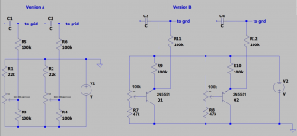
Nothing wrong with version A. But version B has the wiper problem, no contact = no current = grid to ground, no negative no more.I know about the problem with the wiper of the potis.
Any suggestions for a better schematic are welcome.
Inverting the hole circuit and the grid goes to max negative.
Mona
Attachments
The other problem with wipers is that the wipers of carbon potmeters slowly get anodized when there is a DC current flowing out of the wiper, but current into the wiper is no problem.

The other problem with wipers is that the wipers of carbon potmeters slowly get anodized when there is a DC current flowing out of the wiper, but current into the wiper is no problem.
Its a pretty low current you could make the 100k protection R3,R4 resistor 1M in 'A'.
Last edited:
- Home
- Amplifiers
- Tubes / Valves
- What is the best/recommended way to wire the bias trim-poti ?