Hello all,
I know the max stated in the manual is 85VDC from manual...but has anyone pushed this rail voltage around 90VDC successfully?
I have a tranny that is 68VAC. I know quiescent/idle current around 30ma - 100ma as stated in the manual.
Using PSU Designer (inputting primary, series dc resistance) I can get around 92VDC with that 100ma current source...If I put a series resistor of 7ohm before the 10kuf cap, I can get to 88VDC... dont know if adding R for CRC is recommended for class D amps...
Anyway, this calc is highly dependent on current load, and obviously as soon as I am playing music, that current rises and voltage should drop into the safe range...but has anyone successfully built an ICEpower 500 with an 85 - 90 Volt rail at idle/quiescent operation?
Last edited:
Bucking the tranny...
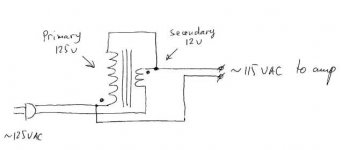
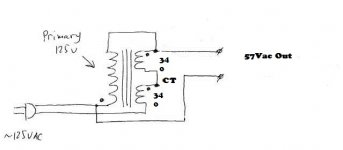
OK, I forgot to mention, its a 34-0-34 tranny...so snooping around the net, I found the first diagram...got me thinking, can I just do second diagram? I am just a Dumba$$ Mechanical Engineer, so go easy on me, por favor...
OK, I forgot to mention, its a 34-0-34 tranny...so snooping around the net, I found the first diagram...got me thinking, can I just do second diagram? I am just a Dumba$$ Mechanical Engineer, so go easy on me, por favor...
Attachments
Last edited:
Both those diagrams are HAZARDOUS. You do NOT want to wire mains to any sort of circuitry where living beings are prone (or pretty much required) to make physical contact, without galvanic isolation.
Galvanic isolation - Wikipedia
What you COULD do would be to wire the two windings in parallel (but make sure they're in phase - see the dots at one end of each winding, in that second drawing), with the associated drop in voltage, and thus, maximum power. Or if you want / need to use this with two of those 500A amps, you could use one secondary for each amp.
Last edited:
Well then... One option would be, for best efficiency, a nice & beefy buck-regulator, to knock down the >90V you'd be getting after rectification and smoothing, down to a less risky 75V or so. Trouble is, i'm not so sure you can find something quite so capable, ready-made. And if you do, it's unlikely to be dirt-cheap.
Yes, I know...does not appear to be a simple solution...
I did find a ton of 1N5354B 17V 5 watt Zener diodes...a string of four of them to get 68VDC?
I have used this 17V 5W Zener on a Tube Amp Power tranny Centertap to drop the B+ ...worked great, but donno if it would work here at these Class D currents...
I did find a ton of 1N5354B 17V 5 watt Zener diodes...a string of four of them to get 68VDC?
I have used this 17V 5W Zener on a Tube Amp Power tranny Centertap to drop the B+ ...worked great, but donno if it would work here at these Class D currents...
Actually, now that I think about it, the last ICEPower 500A amp I built with a DIY power supply, I used a 50VAC-0 transformer, and connected to a pair of the 500A modules at idle, I was right at 63VDC rails, so with the 68VAC-0 transformer, I should be right at 85VDC rails - right at the max limit of the 500A, per the manual...maybe I am OK....
I have a variac, so I can check as I ramp up to full mains voltage... which is rather high where I live - upwards of 126 - 127VAC...but same mains as my last amp...
I have a variac, so I can check as I ramp up to full mains voltage... which is rather high where I live - upwards of 126 - 127VAC...but same mains as my last amp...
Hmmm, does anyone have any experience running the 500A at low voltage rails of 45VDC? I have the 250A modules that would be perfect for this, but was hoping of using the 500A modules...would rather not fry these at the high 85V+Rail...
So what would sound / operate best - a 500A on low 45V rail, or a 250A on typical 45V rail?
So what would sound / operate best - a 500A on low 45V rail, or a 250A on typical 45V rail?
Last edited:
- Status
- This old topic is closed. If you want to reopen this topic, contact a moderator using the "Report Post" button.
- Home
- Amplifiers
- Class D
- What is Max Rail Voltage for ICEpower 500A