I’ll probably make some PSE EL84 amps using the power transformer and some Edcor output transformers I have. I’ll save these outputs for a rainy day.
I’ll probably make some PSE EL84 amps using the power transformer and some Edcor output transformers I have. I’ll save these outputs for a rainy day.
IMO, when you parallel O/P tubes, it's a good idea to employ a C- bias supply and individual (1/tube) bias set trim pots., lest current "hogging" occur. 🙁 Combination bias, with the bulk of the total coming from the C- supply and a small amount from a cathode resistor, gives you both adjustability and stability.
 "Standing" each cathode on a 100 Ω/470 μF. network implements the technique and provides a very convenient "idle" current test point. SS rectify the B+ and voltage multiply the 5 VAC winding to obtain the C- supply. A 4 stage 1/2 wave parallel setup will surely prove adequate. The provided schematic is for a positive rail. So, reverse the polarity of the diodes.
Attachments
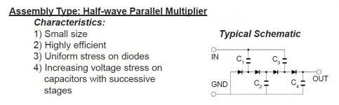
The 1/2 wave parallel idea is not original to me. Check Voltage Multipliers Inc. out.
The schematic shows a 4 stage multiplier, but more stages are fine. Unlike the Cockcroft-Walton (1/2 wave serial) configuration, losses are merely additive and not exponential. 🙂 Nothing but trouble comes free and here the price to be paid is increasing WVDC for the caps. with each stage.
FWIW, I suggest you use Schottky diodes, like this, in the multiplier, for smallest forward drop and least noise.
The schematic shows a 4 stage multiplier, but more stages are fine. Unlike the Cockcroft-Walton (1/2 wave serial) configuration, losses are merely additive and not exponential.
🙂 Nothing but trouble comes free and here the price to be paid is increasing WVDC for the caps. with each stage.FWIW, I suggest you use Schottky diodes, like this, in the multiplier, for smallest forward drop and least noise.
- Home
- Amplifiers
- Tubes / Valves
- What is it?