OK, changed 28 & 29 back to 200R
R28=10mv
R29=21.6mv
R30+D5=76
R31+D6=45.4
R37=12.5
R38=0.1mv
R39=10.7mv
R40=7.0mv
R45=22mv
R46=21.6mv
R47=20.6mv
R48=21.8mv
Offset +65mVdc
R28=10mv
R29=21.6mv
R30+D5=76
R31+D6=45.4
R37=12.5
R38=0.1mv
R39=10.7mv
R40=7.0mv
R45=22mv
R46=21.6mv
R47=20.6mv
R48=21.8mv
Offset +65mVdc
please clarify...some things don't have the m for milli...should I assume volts? Or a missing m?
also...what do you mean by R30+D5?
Ok...leaving all that aside...there seems to be an open in the traces that should connect R38 to R46, or R38 to D10 anode. Can you check those connections?
(power down, ohm-meter?).
I say that because there's no voltage across R38, even though the left edge is common with R40, and the right edge has essentially the same voltage as R40
(e.g. VR46 is about equal to VR48).
Sorry, all should be mv.
I checked and there is good continuity between those connections. I think the issue there is that the bias fluctuates slightly and probably skews my measurements due to time between readings.
Also, since you mentioned D10, I measure 22mv across D10 and 10mv across D9
Since the diode is in between the resistor and ground I measured across them both. I guess this just shows the DC offset.also...what do you mean by R30+D5?
Ok...leaving all that aside...there seems to be an open in the traces that should connect R38 to R46, or R38 to D10 anode. Can you check those connections?
(power down, ohm-meter?).
I checked and there is good continuity between those connections. I think the issue there is that the bias fluctuates slightly and probably skews my measurements due to time between readings.
Also, since you mentioned D10, I measure 22mv across D10 and 10mv across D9
Last edited:
I'm running out of remote control guesses...but I do have another question...
do you see the oscillation on the scope if the load is disconnected?
do you see the oscillation on the scope if the load is disconnected?
hmm...that continues to point in the direction of the soa protection circuits.
There's another way to temporarily disable them, yet leave some of their parasitics in place. Can you get 100 Ohms in parallel with R28 and 100 Ohms in parallel with R29? That would leave a lot of the structure of the SOA circuit in place, just displace the operating point a bit...
It's just a bit finer grained version of the original test that pointed the finger at the SOA circuit...
I think shortly we may reach the end of the remote control trouble-shooting road...although someone else may have other good ideas (or I might, but it's approaching time to zzz's)...
I'm not sure what you are suggesting. Are you saying to add a 100ohm across R28 and another across R29 basically increasing them to 300ohm? I just had 270ohm in there.
I definitely think we are on the right track. Once I disconnected D7 and D8 the oscillation went away. Could what ever is causing the DC offset also cause the SOA to oscillate? Maybe I should be looking at the cause of that.
I definitely think we are on the right track. Once I disconnected D7 and D8 the oscillation went away. Could what ever is causing the DC offset also cause the SOA to oscillate? Maybe I should be looking at the cause of that.
I'm wondering what would happen with increased C17/C18. That would delay the onset of the SOA and may help stop the oscillation.
What do people think?
What do people think?
It would be a good idea for you to post a schematic, with values for the way you have built the amp. There seem to be some differences between what I think you've said, and my reading of the Leach web-site.
So, assuming that R28=R29=200, then placing a 100 Ohm resistor in parallel with each would drop the effective resistance to abut 66 ohms. That should displace the operation point of the SOA circuit, and would give us a bit more data.
A question...is this version built on proven artwork, or on a new, unproven layout?
since we are talking about a control loop within a control loop would it not be a good idea to double check the feedback network and miller compensation? Does this oscillation happen at other frequencies of operation?
mcd...
I think that's a good point...for example, if the miller cap on the bottom weren't loaded, or the wrong value, there could be funny stuff happening.
I think it's also important to know the vintage of the artwork...that lets us know the likely scope of problems...if the artwork is new or unproven, we might be limiting the scope of our questions too much...
djoffe, I agree with knowing the history of the artwork... We shall await info from Terry.
One of the purposes of C17/18 is to compensate the SOA protection control loop. My thinking was increase their values to alter the interaction with the main amplifier loop.
Also, it's interesting that the oscillation appears to be limited to one quadrant of the sine wave.
One of the purposes of C17/18 is to compensate the SOA protection control loop. My thinking was increase their values to alter the interaction with the main amplifier loop.
Also, it's interesting that the oscillation appears to be limited to one quadrant of the sine wave.
Agreed! An increase in those caps (say 2X) would certainly provide some useful data...
Also agree that the oscillation on negative peaks only (or maybe negative rising slopes) gives us more interesting information...if we can only decode it!
Also agree that the oscillation on negative peaks only (or maybe negative rising slopes) gives us more interesting information...if we can only decode it!
Last edited:
Persistence is the key here and going by Terry's persistence so far I don't think he'll give up until all ideas have been exhausted.
I have a feeling we shall decode this information. Just need to fill in the gaps. It would be good to know the frequency of this oscillation.
Increasing the caps by 2x is almost like an even finer test than the two you have already suggested. I've been considering the idea of doubling the miller caps as well. What do you think?
It would be a good idea for you to post a schematic, with values for the way you have built the amp. There seem to be some differences between what I think you've said, and my reading of the Leach web-site.
So, assuming that R28=R29=200, then placing a 100 Ohm resistor in parallel with each would drop the effective resistance to abut 66 ohms. That should displace the operation point of the SOA circuit, and would give us a bit more data.
A question...is this version built on proven artwork, or on a new, unproven layout?
I used the foil pattern provided on the Leach website and etched my boards from that.
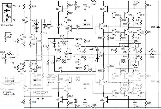
OK here is the schematic
An externally hosted image should be here but it was not working when we last tested it.
Part list I used
D1, D2, D3, D4, D11, D12 - 1N4004 (DigiKey 1N4004DICT-ND)
D5, D6 - 1N4934 fast recovery rectifier
D7, D8, D9, D10 - 1N4148 (DigiKey 1N4148DICT-ND)
D13 through D16 - 1N5250B 20 V Zener
C1 - 390 pF mica
C2, C3, C15, C16, C23, C24, C25 - 0.1 uF, 100 V film
C7, C12, C17, C18 - 0.1 uF, 50 V film
C4, C5 - 100 uF, 63 V radial electrolytic
C6 220 uF, 16 V bi-polar electrolytic
C8 - 180 pF mica
C9 - 47 pF mica
C10, C11 - 15 pF
C13, C14 - 100 uFd 100 V radial electrolytic
C19, D1, D2, D3, D4, D11, D12 - 1N4004
D5, D6 - 1N4934 fast recovery rectifier
C20 - 0.01 uF, 50 V film
C21, C22 - 47 uFd 100 V radial electrolytic
C26, C27 - 270 pF mica
C28 - 0.01 uFd 250 V film
R1 - 20 kohm
R2 - 2 kohm
R3 through R10 - 300 ohm
R11, R12, R27 - 1.2 kohm
R13, R14 - 5.6 kohm 1 watt
R15, R16 - 12 kohm (10 kohm in Ver. 4.3)
R17 - R18 - 11 kohm
R19 - 1.1 kohm
R20 - 22 kohm
R21, R22 - 30 ohm
R23, R24 - 360 ohm
R25, R26 - 1 kohm
R28, R29 - 200 ohm 1/4 watt
R30, R31 - 3.9 kohm 1 watt
R32, R33, R51 - 82 ohm
R34, R35 - 330 ohm (270 ohm in Ver. 4.3)
R36 - 220 ohm
R37 through R40 - 470 ohm 1/4 watt
R41 through R44 - 10 ohm 1/2 watt (changed 6/27/00)
R45 through R48 - 0.33 ohm 5 W Wire Wound
R49, R50 - 10 ohm, 2 W
R52 through R55 - 6.2 kohm 1 watt
R56 through R59 - 10 ohm 1/2 watt
R60 - 39 ohm 1/4 watt
R61 through R64 - 0.33 ohm 5 watt
R65, R66 - 300 ohm 1/4 wat
Q1, Q2, Q5, Q7, Q9, Q10 - MPS8099 or MPSA06
Q3, Q4, Q6, Q8, Q11 - MPS8599 or MPSA56
Q12, Q15 - 2N5415
Q13, Q14 - 2N3439
Q16 - MJE15030
Q17 - MJE15031
Q18, Q20 - MJ15003
Q19, Q21 - MJ15004
Q23, Q24 - 2N3439
Q22, Q25 - 2N5415
Q26 - MJE15030
Q27 - MJE15031
Q28, Q30 - MJ15003
Q29, Q31 - MJ15004
since we are talking about a control loop within a control loop would it not be a good idea to double check the feedback network and miller compensation? Does this oscillation happen at other frequencies of operation?
It does happen at about the same level at all frequencies. I panned through my sine wave generator and it kicked in at about the same place for each. I could easily make another video of that if that would help.
As I said, I have one good channel and one bad. Both built the same.
Last edited:
Another idea, remove C19 and C20. I can see these increasing the chances of oscillation without really improving the effectiveness of the SOA protection.
Might it help to post hi-res pics of the good and the bad board? Perhaps someone could spot a difference that has become invisible to you? (of course, if it's a bad component this great plan falls flat on its face)...
Maybe a close up picture of the problem wave form would be useful. What is the current being drawn from the amp at the point of the oscillation beginning?
I'm just getting back to this hobby after a long hiatus, so please pardon my cobwebs.
Terry, Is the DC offset present without a load as well? Have you tested just the front end, like the basic Leach? There you just tested basic operation, but you could feed is a signal and load it with a 100R and see if a front end issue is causing the offset.
Have you replaced Q10 and Q11? They are cheap. I know others suggested more troubleshooting, but I start with the nickel parts.
Also, since you made your own boards, check continuity of the traces both where they are supposed to connect and where they aren't. Could there be a nearly invisible bridge somewhere especially in the protection circuit. Just run a screwdriver around the traces, see if anything catches.
Of course in my overconfidence, I wonder do you really need the protection circuit? It may help prevent blowing an output device if pushed hard, but it's not going to protect your speakers if a device goes on its own. How hard do you push your amps? Are your speakers kind loads or crazy low impedance/high phase angle beasts? The only time I've blown outputs in the last dozen years was when a voltmeter probe slipped when testing and I shorted a gate to the rails. I've never had one go once I was happy enough with the behavior to hook a speaker up to it. As always, YMMV.
- Status
- Not open for further replies.
- Home
- Amplifiers
- Solid State
- What is it, and where can it be originating from?