Hi All --
I am working on a 6as7 tube amp in another thread with some helpful folks. The topic of using a solid state Constant Current source (CCS) consisting of a couple of transistors has come up. What is this CCS thing and how why does it increase the "swing" of the audio signal? I know a little bit about tubes at this point (long ways to go) but know next to nothing about solid state stuff. Is this technology worth my brain cell bandwidth?? thanks.
I am working on a 6as7 tube amp in another thread with some helpful folks. The topic of using a solid state Constant Current source (CCS) consisting of a couple of transistors has come up. What is this CCS thing and how why does it increase the "swing" of the audio signal? I know a little bit about tubes at this point (long ways to go) but know next to nothing about solid state stuff. Is this technology worth my brain cell bandwidth?? thanks.
Is this technology worth my brain cell bandwidth?? thanks.
That is just priceless.
🙂

Page 133 onward of Morgan Jones - the bible.
Looks complex - took me ages to get my head around. Still don't fully understand MOSFET based CCS devices, but have just figured out MJE350 / MJE340 BJT ones...
Looks complex - took me ages to get my head around. Still don't fully understand MOSFET based CCS devices, but have just figured out MJE350 / MJE340 BJT ones...
Check out the IXYS IXCP10M45S, it's a complete CCS on a chip. All you need is an external pot or resistor to adjust the current and you're all set. You can cascode two of them for a small additional improvement.
I replaced the plate resistor in my Tube preamp with a cascoded pair of the IXYS chips and it transformed the sound; I now get holographic imaging and more gain with no downside I can hear.
I replaced the plate resistor in my Tube preamp with a cascoded pair of the IXYS chips and it transformed the sound; I now get holographic imaging and more gain with no downside I can hear.
I'll bite. Colorado Spinner with night crawlers on the treble hook?
A constant current source is an electronic circuit that provides a fixed current irregardless of the load impedance, within the limits of (1) the supply current, and (2) the thermal limitations of the circuit.
It can be as simple as a two transistor circuit or as complex as a LM317 (or other IC).
In most cases a single resistor is used to set the current magnitude.
How it effects the voltage swing will depend on the circuit in which it is encorperated.
More (specific) details in your question please.
What circuit topology will the CCS be used in?
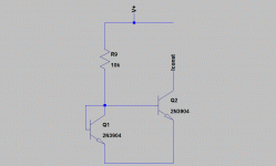
Forget the chip, 2 transistor and a couple of resistor is all you need for a simple CCS. (add a couple more transistors and you can make an excellent CCS.)
A transistors collector current (Ic) depends on the voltage across its base emitter junction (Vbe). Keep that voltage constant and you keep Ic constant(as long as the temperatures are the identical).
In the diagram the 2 trans. Vbe's are identical (wired to be that). The left tran. is conected to turn it into a diode, if the two trans. are identitcal and there Vbe's are the same then there Ics will also be the same. The resistor sets the current tru the diode, which in turn stes the current tru the other trans. That simple!
Attachments
Still don't fully understand MOSFET based CCS devices
Same basic concept -- there is a relationship between Vgs (voltage between the gate and the source) and Ids current from the drain to the source. So, you bias the gate such that there is a voltage difference between source and gate and this will correspond to a particular current flowing across the fet. With a depletion mode fet, like the DN2540, IXYS 10m45, 2sk170, etc, this is particularly easy to do. You simply put a resistor on the source and connect the other side to the gate. As current flows across the resistor, it drops a certain voltage that is used to bias the gate. Enhancement mode fets are biased the opposite way and require an external way to bias the gate -- often a zener and a resistor.
The IXYs chips have measurably better AC performance, parasitic capacitances being what they are in bipolar transistors and even many mosfets, than the simple CCS shown above. This is particularly relevant as tube plate loads where the rp of the tube in question may be significant relative to the load impedance created by the CCS.
I think SY may have touched on this in some ancient posts and I have a number of highly analytical engineer friends who have devised experiments indicating that the more complex cascodes realized with particular mosfets or IXYs CCS chips were able to maintain a very high load impedance over a wide range of audio frequencies whereas the simpler CCS could not.
Depends where the CCS is used - in the case of the cathodes of a 6AS7GA/6080 for example even the 317 configured as a CCS will be adequate because of the low impedances involved relative to those the CCS is capable of generating.
Last edited:
I remember reading a thread here which included a document on the implementation of a two-transistor cascode constant current source for tubes. I think it included values and a pcb design also.
Hang on.... (Gordy goes off and searches around the darkest corners of his hard drive)... yup, it seems to be called "diyAudio-CCS-beta2". Too big to post here. Have a search through the archives and I'm sure you'll be able to find the thread.
Hang on.... (Gordy goes off and searches around the darkest corners of his hard drive)... yup, it seems to be called "diyAudio-CCS-beta2". Too big to post here. Have a search through the archives and I'm sure you'll be able to find the thread.
Change Q2 to a FET and the resistor to 1M and you get a lot more near ideal results.
Forget the chip, 2 transistor and a couple of resistor is all you need for a simple CCS. (add a couple more transistors and you can make an excellent CCS.)
A transistors collector current (Ic) depends on the voltage across its base emitter junction (Vbe). Keep that voltage constant and you keep Ic constant(as long as the temperatures are the identical).
In the diagram the 2 trans. Vbe's are identical (wired to be that). The left tran. is conected to turn it into a diode, if the two trans. are identitcal and there Vbe's are the same then there Ics will also be the same. The resistor sets the current tru the diode, which in turn stes the current tru the other trans. That simple!
I have a number of highly analytical engineer friends who have devised experiments indicating that the more complex cascodes realized with particular mosfets or IXYs CCS chips were able to maintain a very high load impedance over a wide range of audio frequencies whereas the simpler CCS could not.
That's good to know. Thanks.
Meaning no disrespect but I searched on CCS before starting this thread - all I find is references to this ancient text and complements paid to a tube guru named SY. So I thought why not summon this genie for a whole new generation of tube freaks.
Feel free to EMAIL it to me if you want to / can. thx much!
Feel free to EMAIL it to me if you want to / can. thx much!
Here's another...
http://geek.scorpiorising.ca/contrib/Geek/CCS_v0.gif
PCB's are available 🙂
Cheers!
http://geek.scorpiorising.ca/contrib/Geek/CCS_v0.gif
PCB's are available 🙂
Cheers!
It's a wonder you found anything - the search engine doesn't respond to three letter/integer entries, which is extremely annoying given the vast body of information this excludes.
Try google and then look up the diyaudio forum results.
Try google and then look up the diyaudio forum results.
Meaning no disrespect but I searched on CCS before starting this thread - all I find is references to this ancient text and complements paid to a tube guru named SY. So I thought why not summon this genie for a whole new generation of tube freaks.
Feel free to EMAIL it to me if you want to / can. thx much!
Document:
http://homepage.mac.com/tlinespeakers/FAL/downloads/diyAudio-CCS-beta3.pdf
Thread:
http://www.diyaudio.com/forums/tubes-valves/72740-ccs-tubes-valves-pcbs.html
😎
BTW - dsavitsk - you have a terrific website
I have spent a fair amount of time reading stuff on you site - it is well done and well explained - bravo to you sir!! 🙂
I have spent a fair amount of time reading stuff on you site - it is well done and well explained - bravo to you sir!! 🙂
Thx much Gordy!!! Are these boards still around?? I am a newbie to this whole diyaudio world -- I read stuff here for a month or so before saying anything. What a great community -- thanks to all CCS is certainly worth the brain bandwidth - gotta try it myself.
boards are not around any more (the Pinkmouse ones anyway) but there are plenty of others including Geeks (follow the links to his commercial site). As a bit of a noob myself I'd add that once you have the idea, they are not difficult to put together yourself either p2p or on pre-punched board, or try your skills at making a pcb...
A Quick Overview of CCS Options:
1. Two terminal FET constant current diodes (e.g., the CRxxx series) have poor dynamic impedance. They do not perform well unless the tube they're hooked to has very low plate resistance.
2. LM317-based CCS are quite poor. They're fine for things like heater string feeds, but the limited bandwidth and mediocre dynamic impedance make them unsuitable for high quality applications in signal circuits.
3. Degenerated pentodes are excellent current sinks but cannot be easily adapted to make current sources.
4. Degenerated discrete FETs make a much better CCS.
5. The cascode bipolar CCS is cheap, easy, and performs exceptionally well. Gek references an app note I wrote which sums up the design and performance. These devices are covered extensively in Morgan Jones's book (though the good parts aren't Google-able- you need to actually purchase a copy). The limitations as current sources are the lack of high speed high voltage, and high gain in PNP power transistors.
6. Cascoded self-biased depletion-mode MOSFET CCS are even simpler and cheaper (two MOSFETs, three resistors, total cost under $5), with outstanding performance. See, for example, the ImPasse article in February 2009 AudioXpress and Walt Jung's measurements on that CCS a month or two later. These can be equally well used as sources or sinks.
Ccs
Hi,
There are two good articles written by Walt Jung on audioXpress - Home. You can download them from the website: Jung2778.pdf and Jung2779.pdf
The link is: audioXpress - Articles and Addenda
Scroll down 3/4 of the way or do a "Walt Jung" find.
Good luck.
Cheers,
Serge
Hi,
There are two good articles written by Walt Jung on audioXpress - Home. You can download them from the website: Jung2778.pdf and Jung2779.pdf
The link is: audioXpress - Articles and Addenda
Scroll down 3/4 of the way or do a "Walt Jung" find.
Good luck.
Cheers,
Serge
- Status
- Not open for further replies.
- Home
- Amplifiers
- Tubes / Valves
- What is a CCS - how do you design one?