I am in the process of a project converting some speakers to active and will power them with LM3886. The preamp/active crossover is complete but I have too much gain in that stage for the current sensitivity of my LM 3886 implementation which is standard datasheet stuff (gain around 20x). Am I safe to reduce this to 10x or will I encounter stability issues. Thanks. Martin

Reduce the gain of preamp/xover 
Lm3886 sounds best when you set the gain between 24-27db. If you still want to reduce the gain of amplifier section then use all the optional component for stability.
Lm3886 sounds best when you set the gain between 24-27db. If you still want to reduce the gain of amplifier section then use all the optional component for stability.
Ok thanks!Reduce the gain of xover section
Lm3886 sounds best when you set the gain between 24-27db. If you still want to reduce the gain of amplifier section then use all the optional component for stability.
Be sure you don't pre-know how much gain you will really need. Put in a trimmer.
https://www.ti.com/lit/ds/symlink/lm3886.pdf
"LAYOUT, GROUND LOOPS AND STABILITY
The LM3886 is designed to be stable when operated at a closed-loop gain of 10 or greater, but as with any other high-current amplifier, the LM3886 can be made to oscillate under certain conditions. These usually involve printed circuit board layout or output/input coupling. "
The output of the preamp should be attenuated so that the preamp clips soon after the power amp does. Otherwise, you are listening to the preamp noise unnecessarily amplified. It is unwise to push a power amp closed-loop gain down with extra feedback.
That's actually a trick question. In theory you can use (almost) whatever gain you'd like as long as the closed loop gain is 20 dB at ~800 kHz. Most solve this by having a constant gain of at least 20 dB.
Tom
Tom
Would it be a good idea to use LM3886 as a difference amplifier with gain of 5 for both inverted and non-inverted inputs? Will the gain technically still be 10?
No. The relevant search terms are: Loop gain, feedback factor, phase margin. Or see Chapter 8 of Franco. I was told at one point that there's a .pdf version of the third edition of the book floating around on the 'net. Perhaps you can dig it up. It's a pretty straight-forward read.
Tom
Tom
I
I wonder if adding two capacitors to feedback resistors will ensure stability - I simulated few graphs in this post -
https://www.diyaudio.com/community/threads/lm3886-gain-of-5-as-difference-amp.388213/post-7073680
No. The relevant search terms are: Loop gain, feedback factor, phase margin. Or see Chapter 8 of Franco. I was told at one point that there's a .pdf version of the third edition of the book floating around on the 'net. Perhaps you can dig it up. It's a pretty straight-forward read.
Tom
I wonder if adding two capacitors to feedback resistors will ensure stability - I simulated few graphs in this post -
https://www.diyaudio.com/community/threads/lm3886-gain-of-5-as-difference-amp.388213/post-7073680
"You can always attenuate the input signal."
is of course the simplest solution.
https://www.diyaudio.com/community/...886-design-and-pcb-layout.386091/post-7035076
https://www.diyaudio.com/community/...886-design-and-pcb-layout.386091/post-7035701
Patrick
is of course the simplest solution.
https://www.diyaudio.com/community/...886-design-and-pcb-layout.386091/post-7035076
https://www.diyaudio.com/community/...886-design-and-pcb-layout.386091/post-7035701
Patrick
I’m reading more on stability and discovered that I can use the gain of, say 5x, but only if I implement proper lead/lag compensation . It is shown in data sheet as RC network over the feedback resistor.That's actually a trick question. In theory you can use (almost) whatever gain you'd like as long as the closed loop gain is 20 dB at ~800 kHz. Most solve this by having a constant gain of at least 20 dB.
Tom
Also from the data sheet:
At higher frequencies feedback resistance works with Cf to provide lower AC Gain in conjunction with Rf1 and Ri. A high frequency pole (lowpass roll-off) exists at:
fc = [Rf1 Rf2 (s + 1/Rf2Cf)]/[(Rf1 + Rf2)(s + 1/Cf(Rf1 + Rf2))]
where Rf1 is feedback resistor,
Rf2 and Cf is RC lag compensation network.
Will be fun to play with those values in simulator.
Question is, what does a means in the above formula?
It's points plotted on the complex number plane. Useful for filter or oscillator design.
https://eng.libretexts.org/Bookshel..._Design/11.05:_Poles_and_Zeros_in_the_S-Plane
https://eng.libretexts.org/Bookshel..._Design/11.05:_Poles_and_Zeros_in_the_S-Plane
H
HAYK
The best sound I got from LM3886 is with gain of 2.8. You need 1W 180ohm Rf and 1/2W 100ohm Rg. No DC blocking capacitor. To get perfect square wave I need to add 22pF-50pF // to Rf.Question is, what does “s” means in the above formula?
The simulator shows this character.
I use 600-10k transformer ($25 for pair) as input gain.
Nice!
I think Purifi module has gain of 3x. Never heard it but many people like its sound.
And it makes sense since all of that open loop gain is diverted into feedback to correct for errors.
Why such low resistance of 100 and 180 ohms? Not at least 1k?
I think Purifi module has gain of 3x. Never heard it but many people like its sound.
And it makes sense since all of that open loop gain is diverted into feedback to correct for errors.
Why such low resistance of 100 and 180 ohms? Not at least 1k?
H
HAYK
Because of low impedance, the amp remains stable, with 1k it is not.
Try on simulator, you can see how stable it is. The distortion and noise is 7 times lower than with gain of 20, you can check on simulator by comparing the noise.
If you have a working circuit, pass the song Happy Together of the turtles from YouTube, with gain of 20, the refrain will sound dirty but clean with 2.8 as the NFB reaches 40db@20khz.
For the "s" see Laplace transform.
The easiest way to reduce the closed loop gain for the sake of feedback stability without a large gain is a resistor between the + and - inputs, however this may push the common mode range of the inputs beyond their happy voltage. Common mode voltage is a spec that audio amps are not designed for like a general-purpose op-amp. Some older chip amps do not have a LTP input, which is a further complication because the DC voltage at +in and -in are not the same.
Interesting.The easiest way to reduce the closed loop gain for the sake of feedback stability without a large gain is a resistor between the + and - inputs,
Will be digging into that kind of compensation theory and will probably run some simulations just for fun.
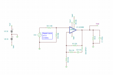
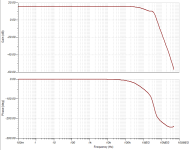
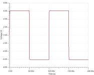
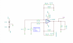
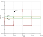
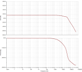
In the meantime, I have simulated my desired gain of 6x and came up with RC values for compensation.
I will need input resistance to be equal or more 3k since I plan on using three LM3886 in parallel - it will give me input resistance of 1k or more.
Right now I am using 4.3k input resistor that should allow for 4.3/3= 1.43K for input impedance.
I am not sure about small value of the compensation capacitor. It is 4.7pF. PCB traces will probably add 1~2pF additional capacitance. Should I try to increase lag cap to 10pF to diminish PCB trace capacitance effect?
Attached are screenshots of TINA-TI simulations.
Attachments
Last edited:
- Home
- Amplifiers
- Chip Amps
- What gain is safe to use for LM3886?