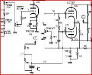
Looking at Hiwatt MI amps. The only standout part of the design is the triode stage that I have highlighted in red in the attached schematic. How does it work? I am confused by how it must interact with the common cathode stage preceding it and the splitter after it.
Attachments

my simple mind tell me it fixes the grid bias on the long tail pair splitters....
first time i have seen it....
first time i have seen it....
Joining the thread for i too am a curious cat.
Looks like some kind of bootstrap for me, bumps the A point higher with signal going to the splitter --> higher gain perhaps?
Looks like some kind of bootstrap for me, bumps the A point higher with signal going to the splitter --> higher gain perhaps?
First time for me as well, but I tend to agree with AJT. Looks like it regulates the bias for the next stage.
my simple mind tell me it fixes the grid bias on the long tail pair splitters....
This. The circuit is a cathode follower. The name is derived from its operation, in which cathode voltage closely follows that of grid, so to speak. The grid voltage, on the other hand, is defined by a resistive voltage divider hooked to a power supply node with the most effective filtering providing most "steady" DC. Because grid voltage is rather independent of cathode current draw the cathode provides a very steady DC reference, in addition the source impedance of the cathode is low, which is a beneficial trait for a voltage source. LTP's grids are then referenced to this voltage source.
I am confused by how it must interact with the common cathode stage preceding it and the splitter after it.
I think it's largely supposed NOT TO interact. As said, the input to the stage is well-filtered DC, which is basically just reduced and then buffered to make the voltage potential in the source to remain constant regardless of current drawn from the source. For the LTP the stage merely serves as a low impedance, steady DC voltage reference. If designed properly it will provide "HiFier" performance than deriving such reference traditonally with an RC filter in the power supply.
In Hiwatt's case this was merely a method to cleverly utilise a triode half that would otherwise remain unused; many other Hiwatt amps directly couple the LTP to preceding stage and the required DC bias is achieved this way.
e.g.
http://hiwatt.org/Schematics/DR_Pre4Input_v0a.gif
If directly coupled, the LTP reference bias voltage is subject to all drifts that the gain stage introduces when operating. When derived from external source the reference bias is free of such interaction.
So, effectively this kind of circuit tries to minimize and remove circuit interactions, not to enhance them.
The other "standout" feature is, BTW, the LTP. The configuration that uses external DC grid bias, instead of deriving it from the cathode circuit, tends to be more common with HiFi amps than it is in guitar amps.
Last edited:
If it helps this version schematic has operating voltages. I still don't get it.
They just had a half triode left over, and used it to buffer the bias voltage for the driver stage.
 This is a guitar amplifier, likely someone over at I & A will have an insight into why a CF was used to generate the bias for the splitter. Moving to Instruments & Amps.
- Status
- Not open for further replies.
- Home
- Live Sound
- Instruments and Amps
- What does this triode do in circuit?