Theoretically biwiring can make difference.
Practically, it makes difference only if you can hear it.
Emotionally, if you invested your gold to purchase extra wires, please do not seek answers, just enjoy your money's worth placebo.
Practically, it makes difference only if you can hear it.
Emotionally, if you invested your gold to purchase extra wires, please do not seek answers, just enjoy your money's worth placebo.
That horse is already dead. And there's no point in beating a dead horse, except, of course, for the sheer joy of it!
I basically missed out bi-wiring and went to bi-amplifying when I discovered how big a difference that made with my then current gear, in the ~80s.
The increased impedance presented to each amplifier by the split crossover reduces the load on the amplifier and thus gives each an easier job.
I like Pano's comment/joke. Fits with my twisted pairs of Flow and Return.
The increased impedance presented to each amplifier by the split crossover reduces the load on the amplifier and thus gives each an easier job.
I like Pano's comment/joke. Fits with my twisted pairs of Flow and Return.
If you respond to any of my posts, would you please read it properly first? (You did a similar thing in a thread when the OP asked about 50W amps into 4 AND 8 ohms, and you suggested the LM3886.) I don't care that you attack me and use pejorative and condescending language but I do ask that your actually read the post first.You are quite incorrect.
It seems that you are unaware of the well-known Fourier theories and tools. That's a pity. They are one of the key foundations of electrical engineering, and of many other disciplines, and are a mental delight. They enable us to both understand and physically manipulate almost any signal, as the sum of a multitude of different frequency components.
Of COURSE the high and low frequency components can be separated!
I understand the Fourier Transform ..............BUT THAT IS NOT WHAT I SAID!. What I said is correct; there is only ONE instantaneous voltage and its commensurate current. The "composite" signal can be de-constructed into its constituent components but it is ONE signal, ie, a single instantaneous voltage.
All bi-wiring is doing is moving the node back to the amp terminals. The question is; does splitting the signal, using the crossover, at the amp terminals make any difference. Is the sum of the signals going "down one wire" any different to the separate signals going "down two wires"? Does superposition not apply?
If you respond to any of my posts, would you please read it properly first? (You did a similar thing in a thread when the OP asked about 50W amps into 4 AND 8 ohms, and you suggested the LM3886.) I don't care that you attack me and use pejorative and condescending language but I do ask that your actually read the post first.
PKB.
I'm sorry if you felt that I attacked you. My intention was to attack only your tactics and arguments. I perceived your posts as tantamount to intellectual bullying (but not necessarily of me).
I understand the Fourier Transform ..............BUT THAT IS NOT WHAT I SAID!. What I said is correct; there is only ONE instantaneous voltage and its commensurate current. The "composite" signal can be de-constructed into its constituent components but it is ONE signal, ie, a single instantaneous voltage.
What caught my eye was when you said, " I was referring, admittedly obtusely, to the supposed HF and LF currents. This notion is as silly as the idea of separating the HF and LF voltages.".
All bi-wiring is doing is moving the node back to the amp terminals. The question is; does splitting the signal, using the crossover, at the amp terminals make any difference. Is the sum of the signals going "down one wire" any different to the separate signals going "down two wires"? Does superposition not apply?
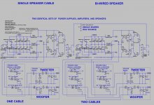
Bi-wiring is the use of separate cables for the high and low frequency speaker currents.
It's not about "the sum of the signals" or superposition, which are obvious. It's probably about reducing crosstalk between drivers.
Speaker cables are relatively lengthy, which means that their parasitic impedances can be significant.
And the signal currents can have large amplitudes and dynamic behaviors, which means that they can induce significant voltages across the individual wires' parasitic impedances, and can also induce significant fields around the cables.
Someone smarter than I am mentioned possible effects from the induced fields. I have been focusing mostly on the effects of the parasitic inductances and resistances of the wires.
I do not expect the effects to be large. But with various crossover topologies and frequencies, the magnitudes of the effects could vary.
Sounds like a tale about two conductors that get lost in a forest..my twisted pairs of Flow and Return.
My first memories of bi-wiring went something like: This isn't working, have I done something wrong?
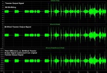
This is giving a scale. Gootee, would you be able to subtract the bi-wired tweeter from the single wired tweeter, and same with the mid?
Can't help yourself, can you?PKB.
Yes, thank you, I thought we had already established that, even to a "dullard" like me.Bi-wiring is the use of separate cables for the high and low frequency speaker currents.
If you took the time to read what I said in CONTEXT then you might extract the meaning I intended. Don't bother though, I really am done and shouldn't have responded. It is pointless when "True Believers" are convinced of something.It's not about "the sum of the signals" or superposition, which are obvious. It's probably about reducing crosstalk between drivers.
To quote my earlier post;
Generally, I've found that people who prone to logical fallacies are incapable of actually seeing their error objectively and do not appreciate the problems and dangers of logical fallacies.
Tom, that difference looks pretty identical to the original signal scaled down (save for polarity reversal from subtraction), which one might expect because of differences in DCR. Or am I not seeing something?
I know what you mean. But there aren't any differences in DCR, or anything else in the circuits, unless I'M missing something. That was one of the beauties of using LT-Spice. Everything was just copied and pasted. So there should be no differences that could account for more than quantization error. And if you think about it, it makes sense that the difference would resemble the original.
Just to rule that out, I'll run a shorter snippet of it with a 10e-02 smaller timestep value.
And I'll upload the sim files.
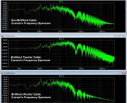
I looked at a lot more than I posted. Zooming in, I was able to see both waveform and FFT differences that i don't believe could have been caused by quantization or timestep issues. I think there are also several places in what did get posted that show true differences, e.g. if you examine the two tweeter waveforms in detail.
I will run it again, this evening. I will also try some other type of signal that might make it more clear.
Just to rule that out, I'll run a shorter snippet of it with a 10e-02 smaller timestep value.
And I'll upload the sim files.
I looked at a lot more than I posted. Zooming in, I was able to see both waveform and FFT differences that i don't believe could have been caused by quantization or timestep issues. I think there are also several places in what did get posted that show true differences, e.g. if you examine the two tweeter waveforms in detail.
I will run it again, this evening. I will also try some other type of signal that might make it more clear.
I am not advocating that bi-wiring works. What I said however is true. It's simple filter behaviour.
There may be HF and LF voltages on both cables however the crossover for the tweeter presents an increasingly higher input impedance at low frequencies. This is part of the mechanism of attenuation. The reverse condition exists for the crossover for the woofer.
This is simple fact.
It's the notion that the fields somehow interfere with each other (since both currents are flowing on the same cable) due to some mystical phenomenon or the non-linearity (passive intermodulation distortion anyone?) of a conductor that constitutes what could be the snake oil.
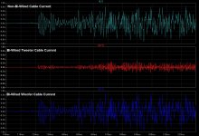
In the attached files R3 is the tweeter cable and R4 the woofer cable. Both see the same voltage from the source however the currents are very different. At the crossover frequency of 1kHz the current in each cable is about 120mA however a decade away at 100Hz the LF current in R3 is 10mA. That's what I am talking about.
Of course the currents are different! The amplifier is a voltage amplifier. If you actually had a more complete model of the amp, cable, crossover and drivers, you would see a bigger difference. If you added in the rest of the impedances (non-perfect components) it gets even far more interesting. In your model, the only difference is the .1 Ohm for the cable. Add in the simple resistance of the coils and see how much less it matters. You are still chasing phantoms.
You are still chasing phantoms.

Wow;
I asserted that the currents are different in the cables that feed the woofer and tweeter. That was all and this was shown.
I wasn't trying to find the holy grail answer to why some people say bi-wiring sounds better. Another poster here said that the currents couldn't be different. My intent was to show that they could be; full stop.
I wasn't trying to find the holy grail answer to why some people say bi-wiring sounds better. Another poster here said that the currents couldn't be different. My intent was to show that they could be; full stop.
People are easily persuaded to believe in things and their existing or not, doesn't really factor into it.
There was a brilliant episode of Penn & Teller's Bul(*&*&%$$, where they set up a "water steward" at a fancy resturant. He had a list of "exotic" waters with wildly different prices, bottles and descriptions (sound familiar yet) of their "tastes". They served the people their "exotic" waters and then filmed them on hidden camera basically regurgitating the descriptions off of the menu.
Cut to scene of the "water steward" filling up all of the bottles from the same hose out in the back of the restaurant.
So you can look for all of the technical justifications you want or might be the source of's, but the real source is the 2lb or so of grey matter inside people's heads.
OK. After some further tests, I "think" a difference has been found.
I did sweeps, stepped sines and dual tones.
Almost no difference in any of those - except. With Bi-Wire running 250Hz and 8kHz, there seems to be less of the 250Hz getting to the tweeter with Bi-Wire. Like 15dB less. I find this hard to believe, but so far it tests out. I won't be able to get back to this for a few days, but that's what I'm seeing so far. Will post a couple of graphs.

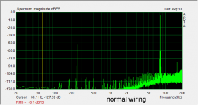
With Bi-Wire running 250Hz and 8kHz, there seems to be less of the 250Hz getting to the tweeter with Bi-Wire. Like 15dB less. I find this hard to believe...
What do you make of these?
That you're right, you shouldn't believe it. Your graphs show a much smaller difference, down near the measurement error/repeatability limits.
Move the lower tone up or down a few Hertz.
Will do, should be able to get to it on Friday. I was careful to write down the levels reported by ARTA, will check again on the next round.
If anyone else cares to do a similar test, it would be nice to see.
If anyone else cares to do a similar test, it would be nice to see.
- Status
- Not open for further replies.
- Home
- Loudspeakers
- Multi-Way
- What does the crossover do differently when you bi-wire?