Sure they are. Because that's what I changed. One set of cables, two sets of cables. The measured difference is because of the different cabling. Can that be duplicated by different, single cable? Probably. Bi-Wiring did make a measurable difference. Is that difference unique to Bi-Wire?Your differences (assuming that the measurement differences were greater than the error bars) aren't because of biwiring.
Can we get Mr. Gootee to model what I measured? Maybe I can give him the L,R,C of the cables I used. Would be interesting to hear what the sims have to say.
Did you use as your control the same two sets of wires in parallel?
That is not consistent.
The setup must be capable of duplicating for single tones. If you double up, then a single tone to either driver will have half the delivery resistance.
jn
Sure they are. Because that's what I changed. One set of cables, two sets of cables. The measured difference is because of the different cabling. Can that be duplicated by different, single cable? Probably. Bi-Wiring did make a measurable difference. Is that difference unique to Bi-Wire?
Can we get Mr. Gootee to model what I measured? Maybe I can give him the L,R,C of the cables I used. Would be interesting to hear what the sims have to say.
Measure the difference between what the tweeters see. Use analog subtraction.
Look for Tabitha's mother.
jn
It doesn't have to cost a fortune to try bi-wiring. Some of the best speaker cable that is commonly available is simple 1.5mm T&E from your local DIY supplier.
It's not pretty, it can be a little difficult to manage, but it's cheap and it's remarkably good cable for speakers.
It's not pretty, it can be a little difficult to manage, but it's cheap and it's remarkably good cable for speakers.
naaahhh...It's already difficult to think of making a set of double send/returns
not to get really inside it...just make the perfect cable, no binding posts 🙄
and on the speaker side, a system that may permit to ear the difference between mono-wiring and biwiring
not to get really inside it...just make the perfect cable, no binding posts 🙄
and on the speaker side, a system that may permit to ear the difference between mono-wiring and biwiring
I prefer Dorcas, the Original Zombie.
Is her character also called Samantha?
jn
No, Hawkshaw.
Ah. I can't think of a modulation technique that would be described by the first three letters HAW.
As opposed to SAM.
jn
AHA.
Haversine Amplitude Windowing.
What happens when the power supply diodes conduct. When they are in conduction, audio signals on the supply rails can be conducted through the power transformer back into the line cord.
Had to stretch for that one...and "Amplitude" isn't floating my boat...I would probably have used Feedthrough. As in Haversine Feedthrough Windowing.
HFW
jn
Sine Amplitude Modulation was so much cleaner.. SAM
The power supply filter capacitors and (if used) inductors should keep the audio from getting into the power supply. That would only happen at very low audio frequencies and at very high audio levels. In such a case, the amplifier would be drawing lots of current. The audio would not be 'leaking' through the power supply. The low frequencies contained in the audio might modulate the secondary of the power transformer due to the current being consumed by the amplifier. The primary of the power transformer should not 'see' this low frequency audio due to the very low impedance of the source .... the power company.
I was once the Chief Engineer for a very high power AM radio station. When I modulated the transmitter with low frequencies, I could see the lights in the building 'flicker' with the audio.
I was once the Chief Engineer for a very high power AM radio station. When I modulated the transmitter with low frequencies, I could see the lights in the building 'flicker' with the audio.
The power supply filter capacitors and (if used) inductors should keep the audio from getting into the power supply. That would only happen at very low audio frequencies and at very high audio levels. In such a case, the amplifier would be drawing lots of current. The audio would not be 'leaking' through the power supply. The low frequencies contained in the audio might modulate the secondary of the power transformer due to the current being consumed by the amplifier. The primary of the power transformer should not 'see' this low frequency audio due to the very low impedance of the source .... the power company.
I was once the Chief Engineer for a very high power AM radio station. When I modulated the transmitter with low frequencies, I could see the lights in the building 'flicker' with the audio.
Your statement is in theory correct, they should keep audio from the power supply.
Audio bleed into the line cord is a measured entity.
Given your work history, you know about four wire caps. Lytics certainly don't fit that type, and nobody worries about loop coupling via mutual inductance in an audio amp power supply.
But let's not get OT. Biwire mods is dejour...
jn
Actually, the (active) crossovers are not expensive. This is the DIY forum! ...
Well, certainly if you don't value your time, and certainly if you know how to design active filters, and certainly if you can create low noise circuit boards, and certainly if you have the time, you can build your own crossovers.
Though to the best of my knowledge, Active Crossovers of any slope are built around capacitors, resistors, and Op-Amps, coils are not needed.
Obviously, if you can do it yourself, and you don't put a price on your time, and if you have the equipment necessary, then you can prototype and build your own Active Crossovers.
But, in the details, that is a pretty high learning curve. However, if you value learning, then the experience has value that offsets the time and cost.
Steve/bluewizard
I easily can see the benefits of bi-wiring but I decided to work on an improved speaker cable that gained many of the same advantages with very low DCR and good high-frequency characteristics so haven't bi-wired yet.
Bi-wiring can definitely help in an instance where the back emf of a bass driver varies with the signal and would leak into the HF section unless it were stopped using amplifier feedback.
Bi-wiring can definitely help in an instance where the back emf of a bass driver varies with the signal and would leak into the HF section unless it were stopped using amplifier feedback.
Bi-wiring can definitely help in an instance where the back emf of a bass driver varies with the signal and would leak into the HF section unless it were stopped using amplifier feedback.
I think Gootee has clearly shown that this is not the case.
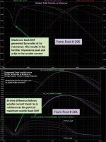
The back emf from a bass driver is maximum at its resonance frequence.
This back emf results in the familiar impedance peak at resonance and a dip in the woofer current.
The main difference(<10kHz) between the tweeter response for the bi-wire and standard single wire case arises from the incremental voltage drop across the single wire from the woofer current which doesn't exist in the bi-wire case. The attachment pulled from Gootee postings clearly shows that the differences in tweeter response follow the woofer current trend.
Attachments
I'm considering magnetic field linearity - what about all the harmonics up to the xover point and beyond that are riding on the cone as it moves - they all contribute to the back emf. Mud magnet speakers are particularly susceptible to effects like this with their AC modulation.
As another example, I had a 15" guitar speaker I used as a test load when designing an amplifier which had a voice coil rub that definitely affected its back emf at any frequency that it was excited at. It could be easily seen with an oscilloscope. By increasing the amplifier's feedback I was able to totally cancel out the effect of the vc rub back emf at the amplifier's terminals. But if you had a speaker cable with more than a few hundred milliohms impedance, enough of that back emf could leak right through the xover to the mid or hi end driver and be heard.
As another example, I had a 15" guitar speaker I used as a test load when designing an amplifier which had a voice coil rub that definitely affected its back emf at any frequency that it was excited at. It could be easily seen with an oscilloscope. By increasing the amplifier's feedback I was able to totally cancel out the effect of the vc rub back emf at the amplifier's terminals. But if you had a speaker cable with more than a few hundred milliohms impedance, enough of that back emf could leak right through the xover to the mid or hi end driver and be heard.
Last edited:
To the contrary - what about all the harmonics up to the xover point and beyond that are riding on the 'resonance'? - you can't find any rule or law that exempts them from exactly the same back emf changes due to varying magnetic field due to excursion.
I think I see what you are getting at. Excellent point.
Any higher frequency current distortion produced in the woofer voice coil due to flux modulation during large woofer excursions, would produduce incremental voltage drops on the single wire and fed to the tweeter, which bi-wiring would minimize/eliminate. This non-linear effect is not included in the simple Gootee woofer model.
- Status
- Not open for further replies.
- Home
- Loudspeakers
- Multi-Way
- What does the crossover do differently when you bi-wire?