Hello,
After many try-outs of my previous project (and after a blown speaker and several transistors) I've decided to start something new. I've build a good and stable power supply which consists of 8 transformers (230v => 1 x 35v , 4A) and 6 capacitors (6 x 37000 µF). I also want to thank all the people who helped me with my previous project, but I can't solve all the problems (the problem of oscillation is solved, but now a DC-current appears at the output).
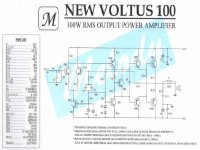
So I started to search some amplifier designs which match to my power supply (2 x 50V/16A). If this amp (http://members.tripod.com/valveaudio/images/schematics/voltus100.JPG) works well, I want to build four of them, so I can bridge (2x) two amps together to make a amplifier of 2 x 400W (also see http://members.tripod.com/valveaudio/images/schematics/bigvoltus1.JPG).
What do you think of the included schematic?
Best regards,
HB.
After many try-outs of my previous project (and after a blown speaker and several transistors) I've decided to start something new. I've build a good and stable power supply which consists of 8 transformers (230v => 1 x 35v , 4A) and 6 capacitors (6 x 37000 µF). I also want to thank all the people who helped me with my previous project, but I can't solve all the problems (the problem of oscillation is solved, but now a DC-current appears at the output).
So I started to search some amplifier designs which match to my power supply (2 x 50V/16A). If this amp (http://members.tripod.com/valveaudio/images/schematics/voltus100.JPG) works well, I want to build four of them, so I can bridge (2x) two amps together to make a amplifier of 2 x 400W (also see http://members.tripod.com/valveaudio/images/schematics/bigvoltus1.JPG).
What do you think of the included schematic?
Best regards,
HB.
Hi Hugobross,
If you compare the schematic you are providing with the GAS Son of Ampzilla schematic you will see the Son has all complementary circuitry:
http://home.earthlink.net/~narf1/sonamp.jpg
I think the Son is a better sounding amplifier. What a pity GAS is out of business for 25 years. Its circuit was ahead of time!
The output transistor TIP 2955/3055 is rated for 90W only. The TIP 35/36 is rated for 125W only.
MP
MP
Hugobross
Palesha is right. For sure with just one pair tip3055/2955 you will have problems with this amp, if you use it at continuous high power levels. With TIP35/36 I think it can work, but the output transistors will suffer. Two pairs per channel will do the job very well.
regards
Palesha is right. For sure with just one pair tip3055/2955 you will have problems with this amp, if you use it at continuous high power levels. With TIP35/36 I think it can work, but the output transistors will suffer. Two pairs per channel will do the job very well.
regards
It must be pointed out that both the TIP 3055/2955 and the 35/36 pairs have a safe area that folds back above 30V, in reality they can only handle 50W at 50V and that is at room temperature. With typical heatsinking and mounting I would say 10W per device. This means that a pair would be adequate for a 50W class AB amplifier. While the 35/36 are available in the 'C' or 100V range the 100V rating on the 3055/2955 is only when reversed biased. When forward biased in a class AB amplifier they must be resricted to +/- 30V. NAD tried to use these with +/-40V in several designs. When they blew up I replaced them with MJ15015/15016, which are 3055/2955 die family that have been selected for high voltage. TR4/5 are listed as MPS A06/A56, they can only take +/-40V, in case you haven't figure it out yet this design is a waste of time and money. On the other hand http://valveaudio.tripod.com/images/schematics/400w.jpg with MJE15030/15031 for drivers will do what you want with two pair of outputs per bridge half. This is exactly the same tripple darlington output stage as in a Crown Macrotech 1200, they use the MJE15030/15031 as drivers and MJ15003/15004 as outputs. If you see beefing up the supply someday and driving 2 ohms, build it as shown with four pair of outputs per bridge half.
Hugo,
This design is better than your previous project, but, again, the safety margin is too low. Tou have to consider all given advices, and use quality transistors for the output stage, in suffiscient quantity, otherwise you will burn transistors and speakers again and again.
Generaly speaking, 3055 or similar devices exhibit poor gain and linearity, and have to be used only for public adress, not for high-fidelity purposes.
TIP 35/36 C are usable, but with at least 3 pairs in the output stage, in order to maintain collector current in safe limits if the amplifier is overloaded. Each transistor must have its own resistor in the emitter connection, as usual.
MJE 15030/31 are the good choice for the drivers. Don't use another devices, these are specially designed for hi-fi driver purpose, and work very well.
Ragards, P.Lacombe
ONE pair of MJ15003/15004 have MORE safe area than FOUR pair TIP35/36 at 50V at elevated temperatures. This is entirely because of the plastic cases on the TIP parts. Yes, you can make an amp that will work with plastic outputs. But for how long? And how much is it going to cost to replace those woofers and crossover parts when the amp 'grenades' a couple of years down the road? A relay you say? Don't make me laugh! Relay contacts will arc and then weld when trying to open DC into an inductive load. Add a 'crowbar' circuit with a triac if you are going to use plastic.
relays == bad?
djk, you say in your reply that relays will arc and weld when tripped during overload. Have you acutally seen this happen?
I am curious to know, because in Slone's amp design book, he reccomends relays over crowbar circuits, which is in direct contrast to your advice.
It is hard for me to imagine a relay arcing. I say this because most amps I see have rails of 80V or less. I don't think 80V is enough to cause an arc. Wouldn't the short of the output cause the rails to drop potential because of the limited current supply also? Also, would the relay arc before the protection fuses blow?
In addition, the particular design I am building is based on lateral MOSFETs. Slone indicates in his book that the vast majority of lateral MOSFETs fail "soft", which is to say that when they go, they will short the gate to source instead of emitter to collector like BJTs. Does this failure mode have any relevance to relay arcing?
I would like to know more about your experiences.
"djk, you say in your reply that relays will arc and weld when tripped during overload. Have you acutally seen this happen?" Are you kidding? More times than I can count.
"I am curious to know, because in Slone's amp design book, he reccomends relays over crowbar circuits, which is in direct contrast to your advice." So what.Do you want protection or not? "It is hard for me to imagine a relay arcing." In Electronics 101 they teach that an inductor will try to maintain the current through itself.If you try and interupt the current, ie open the relay while driving DC into an inductive load, the back EMF will try to rise to infinity.Is that high enough to arc? "Also, would the relay arc before the protection fuses blow? " A fast blow, AGC type fuse, will pass 200% of rated current for one hour.If correctly sized they will prevent fire after amplifier failure.I used to fix a lot of Crown DC300A, Peavey CS800, etc.When the customer brought them in the first thing I checked was the fuse.If it had the ABC ceramic fuse I told them it wasn't bad.If they had put in an AGC glass fuse I told them it would be a bunch of money.The fuse element melts and tries to open up under overload.Then because of the inductive load the voltage rises and an arc is struck through the metal vapor of the fuse.ABC fuses have powder in them to quench this arc.The extra energy carried by the arc wipes out emitter resistors, bridge rectifiers, and crowbar triacs that normally would not have failed. "Slone indicates in his book that the vast majority of lateral MOSFETs fail 'soft', which is to say that when they go, they will short the gate to source instead of emitter to collector like BJTs. " This is true but the lateral MOSFET is very expensive on a safe area watt per dollar bassis and I don't care for the sound of the bass of amps using these kind of outputs.
"I am curious to know, because in Slone's amp design book, he reccomends relays over crowbar circuits, which is in direct contrast to your advice." So what.Do you want protection or not? "It is hard for me to imagine a relay arcing." In Electronics 101 they teach that an inductor will try to maintain the current through itself.If you try and interupt the current, ie open the relay while driving DC into an inductive load, the back EMF will try to rise to infinity.Is that high enough to arc? "Also, would the relay arc before the protection fuses blow? " A fast blow, AGC type fuse, will pass 200% of rated current for one hour.If correctly sized they will prevent fire after amplifier failure.I used to fix a lot of Crown DC300A, Peavey CS800, etc.When the customer brought them in the first thing I checked was the fuse.If it had the ABC ceramic fuse I told them it wasn't bad.If they had put in an AGC glass fuse I told them it would be a bunch of money.The fuse element melts and tries to open up under overload.Then because of the inductive load the voltage rises and an arc is struck through the metal vapor of the fuse.ABC fuses have powder in them to quench this arc.The extra energy carried by the arc wipes out emitter resistors, bridge rectifiers, and crowbar triacs that normally would not have failed. "Slone indicates in his book that the vast majority of lateral MOSFETs fail 'soft', which is to say that when they go, they will short the gate to source instead of emitter to collector like BJTs. " This is true but the lateral MOSFET is very expensive on a safe area watt per dollar bassis and I don't care for the sound of the bass of amps using these kind of outputs.
"I am curious to know, because in Slone's amp design book, he reccomends relays over crowbar circuits, which is in direct contrast to your advice." So what.Do you want protection or not?
Protection I would like, but I could sure do without the rudeness.
If my post came across as accusatory, then I apologise, I meant no offense. I am only trying to reconcile the two opinions.
Since you obviously have much experience with design reliability, you are one of the best resources I have seen on this forum. Your posts are informative, and include examples. However, the reason I am mentioning Slone is that he is no idiot. I am not going to dismiss an author with 30+ years of design experience in home and commercial audio lightly.
Does the inductance of the load affect the magnitude of the back EMF? Is this a problem with any speaker, or is there a greater risk with only certain kinds? Most crossover networks are not purely inductive. Does the capacitance have any additional effect?
A relay keeps the amp quiet during turn on and turn off. A crowbar will protect the load from DC. You can build an amp with either or both. The amps that I have seen that had both seem to run forever because the designer didn't cut corners in other areas either. The only work of Sloan that I have seen is the 200W MOSFET job from Radio Electronics about three years ago. There was plenty of room for improvement in that design. The woofer is the big culprit for inductance.
thanks for replying!!
I didn't checked out the safety-margin of the outputdevice, but I learned I will check that first before even thinking about building a new project. It's amazing how many published designs have too small safety margins. I think MJ15003/15004 (250W) is the best pair to use in this amp.
Thank you all !!!
HB.
Hugobross,
I remember now you can use TIP35/36 D, E or F type in this amp. Two pairs might be enough for 8 ohms loads without "blow ups". The pdf file for these devices is below:
regards
I remember now you can use TIP35/36 D, E or F type in this amp. Two pairs might be enough for 8 ohms loads without "blow ups". The pdf file for these devices is below:
regards
A the risk of repeating myself "ONE pair of MJ15003/15004 have MORE safe area than FOUR pair TIP35/36 at 50V at elevated temperatures. This is entirely because of the plastic cases on the TIP parts. Yes, you can make an amp that will work with plastic outputs. But for how long? And how much is it going to cost to replace those woofers and crossover parts when the amp 'grenades' a couple of years down the road? A relay you say? Don't make me laugh! Relay contacts will arc and then weld when trying to open DC into an inductive load. Add a 'crowbar' circuit with a triac if you are going to use plastic." What part of that didn't you understand? See figure #6, forward bias safe area http://www.mospec.com.tw/pdf/power/TIP35D.pdf
- Status
- Not open for further replies.
- Home
- Amplifiers
- Solid State
- What do you think of this amp?