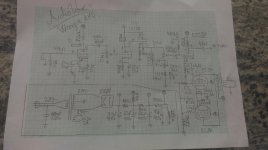
I haven't spotted any obvious flaws, for whatever that's worth.Before I start to build anything I want to make sure that the amp is okay.
I have a question, why the somewhat higher-current operation of the second triode? (820 ohm Rk / 55k Ra)
Oh, come on! Your drawing is very neat! Nicely done!Excuse my bad drawing... but i hope it is readable.
-Gnobuddy
I have a question, why the somewhat higher-current operation of the second triode? (820 ohm Rk / 55k Ra)
Just a mistake I made, all resistors in preamp are now changed to 100k value.
Thanks, your checking means lot to me.
The EL86 seems to be running both "hot & cold" - hot: you need to back down the screen voltage (may be the plate as well); cold: you need to change the cathode resistor to a smaller value - look at the datasheet for a good starting point... BTW, do you know the primary impedance of the OPT?
The EL86 seems to be running both "hot & cold" - hot: you need to back down the screen voltage (may be the plate as well); cold: you need to change the cathode resistor to a smaller value - look at the datasheet for a good starting point... BTW, do you know the primary impedance of the OPT?
We've yet had this discussion: Plate voltage will be on the very high side, hence he has to bias the valves at lowish plate currents for not to exceed the dissipation ratings. Thus he needs an OPT of comparatively high load impedance, but sacrifices lot of possible output power.
Btw, he told us that his OPT comes from an old EL34 radio. So it's primary impedance can be assumed to about 2 to 3 kOhms - but at a secondary impedance of 5 ohms which was very usually in those days. Now he has a speaker of 8 ohm, hence the primry impedance will increase by a factor of 8/5. Leaves us curious on the results🙄...
With two EL86 and a plate supply voltage of nearly 400 volts, I'd go for the SEPP design Philips these valves had developed for. Look for the AG9015 schematics to get some hints. For guitar amplification use, a cheap 230/24V 30VA toroid will provide the optimal load impedance of about 800 ohms.
Best regards!
I know, but we were just guessing without a schematic in front of us. Now looking at the latest schematic, the operating conditions look pretty poor even for a guitar amp... Yup, the Philips SEPP or the Orgaphon is looking better by the minute.
Yup... pretty poor for a guitar amp...
The reason behind all this values is:
I ordered 300 various values resistors
200 values capacitors and some other things
So I am building an amp that uses the components that I already have.
And I am passing with a 110$ bill for the whole amp...
All from eBay costed me 55$
Matched pair EL86 tubes 15$
4 pieces ECC88 gold grid 10$
EZ81 10$
Old beefy radio: 20$
You misunderstood, I was referring to the output stage only. If you don't fix it, it won't work very well, perhaps even self-destruct.
sounds like the sort of thing only Tubelab George regularly manages to pull off!
I built a guitar amp for the Hundred Buck Amp challenge that used UL84's which are derived from the 6CW5 / EL86, not the EL84. They will indeed eat plate voltages in the 400+ volt range, but the screen voltage MUST be kept in the 200 volt or less range.
My amp used an isolation transformer and a SS voltage doubler for power producing about 330 volts and 165 volts for the screens. The OPT was an Antek mains toroid for a load impedance of about 3500 ohms. The amp made about 20 watts clean and close to 30 watts of screamin clipped square waves. I never tried to squeeze 40 watts from them though.
The schematic that I used to lay out the PC board is included. After building it, I found way too much gain and the variable gain mosfet stuff in the cathodes of the preamp tubes did not work so several mods were made.
All the mosfets in the cathodes were removed, and replaced with resistors to set the gain of each stage. Mosfet buffers Q1 and Q6 were removed to reduce the gain.
It all started when I was 11 yrs old... I wondered how my dad's Fender works
I was 9 or 10 when I "made" my first guitar amp by cutting a guitar cord in half and twisting and taping the wires from the guitar cord to the pick up wires in the record player of an old Magnavox HiFi set. By 12 or so I was building guitar amps out of parts removed from discarded TV sets.
Attachments
Thank you for spotting that... I will try to fix it, currently I am fixing the schematic...
The best idea I currently have is to put that OPT somewhere else, lower the plate voltage, and make a better bias.
The best idea I currently have is to put that OPT somewhere else, lower the plate voltage, and make a better bias.
- Status
- Not open for further replies.
- Home
- Live Sound
- Instruments and Amps
- What do you think about this tube schematic?
