Hi
When you shop for an Amplifier board, it's hard to miss the Coils there.
What is their purpose?
Thank you
When you shop for an Amplifier board, it's hard to miss the Coils there.
What is their purpose?
Thank you
Last edited:
You have coils in class D amplifiers where they serve in the output filter. The output filter converts a PWM modulated signal, switching between the positive supply rail and ground, into an average value (that varies with the duty-cycle). This average value signal from the filter output is the signal used to drive the speakers.
Well explained on Wikipedia: Class-D amplifier - Wikipedia
Well explained on Wikipedia: Class-D amplifier - Wikipedia
Last edited:
Interesting..
I was sure the amplifier outputs the needed voltage values byitself, not PWM..
Nice to know how Class D amplifiers work.
Another thing regarding the Coils in Class-D amplifiers:
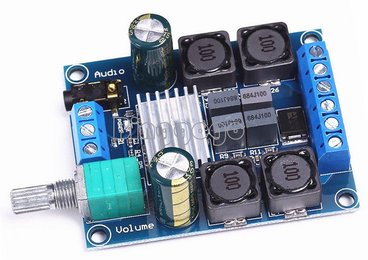
In the first picture above, the coil components have a certain look,
but in this different board here in the following image, the coils look smaller,
and without a cover from the sides:
(the board has the same chip: TPA3116D2)
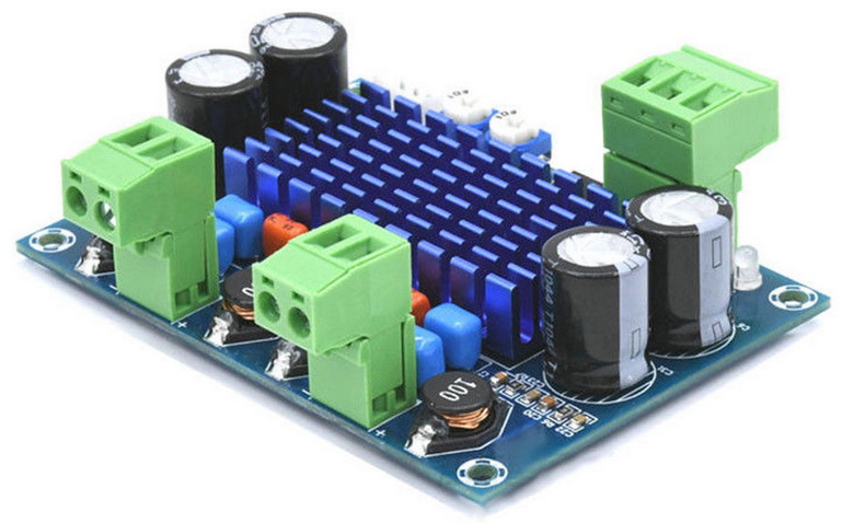
As can be seen,
it also has 4 coils,
but they look smaller, and are not covered from the sides..
Since both boards are the same amplifier chip - TPA3116D2,
should a person who wants to buy such amplifier deduce that the board with the smaller coils is less good than the board in the first image?
I was sure the amplifier outputs the needed voltage values byitself, not PWM..
Nice to know how Class D amplifiers work.
Another thing regarding the Coils in Class-D amplifiers:
In the first picture above, the coil components have a certain look,
but in this different board here in the following image, the coils look smaller,
and without a cover from the sides:
(the board has the same chip: TPA3116D2)
As can be seen,
it also has 4 coils,
but they look smaller, and are not covered from the sides..
Since both boards are the same amplifier chip - TPA3116D2,
should a person who wants to buy such amplifier deduce that the board with the smaller coils is less good than the board in the first image?
The coils in the first photo are enclosed ferrite chokes. They (10uH/"100") can probably handle some 5A current (peak) before saturation.
The coils on the second photo are partly open ferrite chokes where the magnetic field is running in the air as well. Saturation should be less of a problem but I cannot tell you the saturation value. The open design leaves more radiated noise.
As a very rough rule of thumb: the bigger the choke (physical size) and the less inductance value, the more current it can handle before saturation.
Again, I will refer you to Wikipedia for further studies: Choke (electronics - Wikipedia)
Last edited:
Interesting.
Regarding the second board, with partly open ferrite chokes,
you wrote:
This means that If 2 coils are quite close to each other, then the signal can mix or deviate a little bit?
In that case the open design seems like a bad option..
(saves 1-2 cents for the mfrr, but makes a worse product)
Regarding the second board, with partly open ferrite chokes,
you wrote:
The open design leaves more radiated noise.
This means that If 2 coils are quite close to each other, then the signal can mix or deviate a little bit?
In that case the open design seems like a bad option..
(saves 1-2 cents for the mfrr, but makes a worse product)
The extreme is air-coils without ferrite. They do not saturate or have core-losses. They tend to be rather big and the magnetic field may couple to other components or conductive surfaces such that noise or losses are introduced. Anyway, a class D amplifier is noise-wise a mess with high amplitude square-wave signals and high slew-rates. It is the output filter that in the end brings back a useful signal for the speakers.
Even air-coils have supporters among audiophiles.
Personally, I prefers chokes with ferrite cores because the magnetic fields are rather confined and the windings needed are much less than for air-coils. But, I have to live with core-losses and always take saturation into account in the design.
Even air-coils have supporters among audiophiles.
Personally, I prefers chokes with ferrite cores because the magnetic fields are rather confined and the windings needed are much less than for air-coils. But, I have to live with core-losses and always take saturation into account in the design.
Last edited:
Really interesting..
BTW..
This is a 3rd board, for the same amplifier chip:
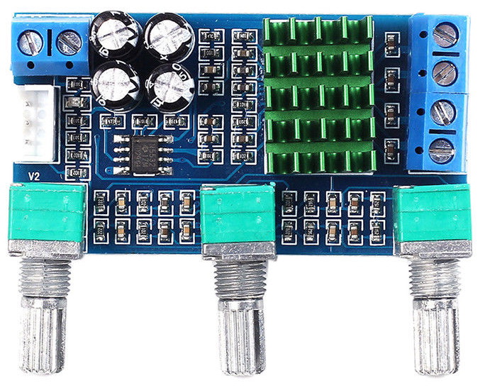
We cannot see here anything that looks like a coil,
but since most components on this board are SMD, then I assume that they used SMD coils here..
Probably the column of 4 components on the right,
exactly between the heatsink and the 4 screw-connectors..
If these 4 components are indeed coils, then they are really small.
Should we now deduce that this will be the worst of the 3 boards?
(so small coils)
BTW..
This is a 3rd board, for the same amplifier chip:
We cannot see here anything that looks like a coil,
but since most components on this board are SMD, then I assume that they used SMD coils here..
Probably the column of 4 components on the right,
exactly between the heatsink and the 4 screw-connectors..
If these 4 components are indeed coils, then they are really small.
Should we now deduce that this will be the worst of the 3 boards?
(so small coils)
As explained above, the coils form part of a low pass filter that filters out the switching frequencies from the output, leaving just the audio signal (mostly).
I have a number of Class-D amps that use toriod cores for the coils. Most you see these days have surface mount ferrite coils like in your photos. I've used air core, but they are large and can radiate RF, as FF explained.
I have a number of Class-D amps that use toriod cores for the coils. Most you see these days have surface mount ferrite coils like in your photos. I've used air core, but they are large and can radiate RF, as FF explained.
In theory you don't have to have the output filter caps and coils. Since the square waves at the output are of the same polarity, no RF current should low thru the speaker, only AF. But things are never perfect and there will be RF some current and plenty of RF noise radiated into the air.Should we now deduce that this will be the worst of the 3 boards?
(so small coils)
In all 3 boards the coils are SMD,
but in the 3rd board, If my assumption is right, then the coils are tiny, like SMD resistors..
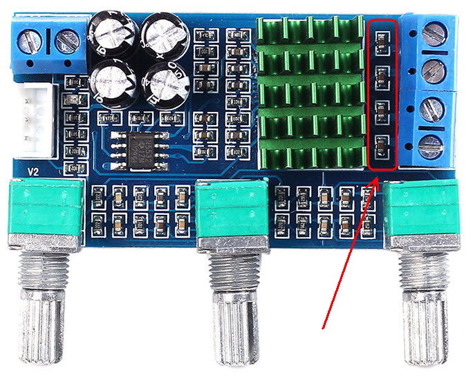
I was talking about these 4 components:
If those are indeed SMD Coils,
are they inferior in their work compared to the bigger ones?
but in the 3rd board, If my assumption is right, then the coils are tiny, like SMD resistors..
I was talking about these 4 components:
If those are indeed SMD Coils,
are they inferior in their work compared to the bigger ones?
No, the third board actually has no LC output filter. Why? Because TI writes in their TPA3116 datasheet that such is possible.
In reality it is not a good idea without a real output filter. This design relies on the speaker cables and the inertia of the speaker drivers to act as a low pass filter. Neither is relying on a rather poorly defined filtering effect good engineering in my eyes, nor does this always function well in practice. When you send power square-wave signals out on the speaker wires, the speaker wires act as antennas. Radio reception is one problem as experienced by a forum member who could hardly receive FM signals.
The four small components you have marked are SMD capacitors (ceramic).
If you end up with a board like the third board you show, add an output filter yourself.
Last edited:
Wow..
Amazing.
I didn't think that asking about the coils in Class-D amplifiers would bring all this up.
Thank you so much
And after all this info, I trust the first board the most..
Amazing.
I didn't think that asking about the coils in Class-D amplifiers would bring all this up.
Thank you so much
And after all this info, I trust the first board the most..
I have the first board among more TPA3116 boards and it is really value for money. With the usual "hiss" issue as described thoroughly in other postings.
Hmm
So despite the hiss it is still a great value for money?
Is the hiss heard even in relatively low volume, or only in loud volume?
So despite the hiss it is still a great value for money?
Is the hiss heard even in relatively low volume, or only in loud volume?
The hiss is at mid position of the volume potentiometer. It can easily be removed by lowering the gain to 20dB or inserting two 4K7 at the outputs of the of the volume potentiometer. If you search for "TPA3116" and "hiss" you will find many explanations on how to solve this problem.
BTW
I have a link saved from maybe 6 years ago,
it is also a TPA3116D2 board, but a bit special:
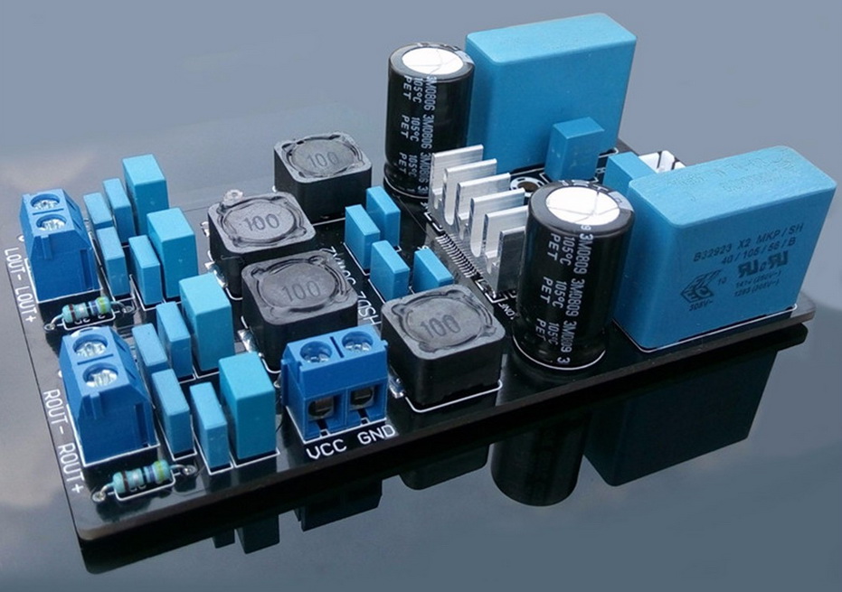
50W+50W TPA3116D2 Digital Power Amplifier Board Official Version Sale - Banggood.com
As can be seen,
the designer of this board really likes box capacitors 🙂
Well I can understand him.
They look nicer than regular electrolytic capacitors..
I wonder tho what effect on sound they have, and i it's even noticeable..
I have a link saved from maybe 6 years ago,
it is also a TPA3116D2 board, but a bit special:
50W+50W TPA3116D2 Digital Power Amplifier Board Official Version Sale - Banggood.com
As can be seen,
the designer of this board really likes box capacitors 🙂
Well I can understand him.
They look nicer than regular electrolytic capacitors..
I wonder tho what effect on sound they have, and i it's even noticeable..
Not necessarily.In all 3 boards the coils are SMD,
but in the 3rd board, If my assumption is right, then the coils are tiny, like SMD resistors..
I was talking about these 4 components:
If those are indeed SMD Coils,
are they inferior in their work compared to the bigger ones?
You have no clue on how Class D or inductors work, and are trying to separate bad from good based on a not-so-relevant visual clue; it does not work that way.
What matters is an electrical parameter, which is inductance, and is printed on coil body ... as long as coil measures that (and I guess all do, unless proven contrary by experiment or measurement) then all are equally fit for the task.
Another electrical parameter, NOT printed anywhere but found on the datasheet, is saturation current, but you don´t know (nor do we) until actually reading those datasheets.
Do you have any links to them?
50W+50W TPA3116D2 Digital Power Amplifier Board Official Version Sale - Banggood.com
I wonder tho what effect on sound they have, and i it's even noticeable..
It seems like a fine board.
I have links to the board pages (in eBay, etc),Do you have any links to them?
but not to the datasheets of the components they used..
So we cannot know more than the pic shows..
- Home
- Amplifiers
- Class D
- What do the Coils do, in Amplifiers?