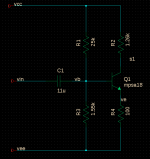
In this simple common emitter stage there's an intentional pole at 10hz at the input and an intentional 180 phase shift due to the CE stage inverting gain stage but I want to understand what model parameter causes the 360 phase shift. Also, is this something I need to be concerned about? Rails are +/- 15V.
Here is the model:
.model mpsa18 npn (
+ Is=33.58f Xti=3 Eg=1.11 Vaf=100 Bf=2.365K Ne=1.579
+ Ise=166.7f Ikf=.1172 Xtb=1.5 Br=5.774 Nc=2 Isc=0 Ikr=0 Rc=1
+ Cjc=4.948p Mjc=.4109 Vjc=.75 Fc=.5 Cje=7.547p Mje=.3765 Vje=.75
+ Tr=800.3p Tf=310.1p Itf=.6 Vtf=6 Xtf=35 Rb=10)
Here is the model:
.model mpsa18 npn (
+ Is=33.58f Xti=3 Eg=1.11 Vaf=100 Bf=2.365K Ne=1.579
+ Ise=166.7f Ikf=.1172 Xtb=1.5 Br=5.774 Nc=2 Isc=0 Ikr=0 Rc=1
+ Cjc=4.948p Mjc=.4109 Vjc=.75 Fc=.5 Cje=7.547p Mje=.3765 Vje=.75
+ Tr=800.3p Tf=310.1p Itf=.6 Vtf=6 Xtf=35 Rb=10)
Attachments
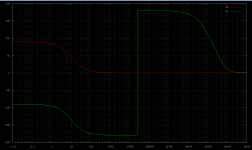
If I understand your question correctly you mean the vertical line at ~20kHz?
This is just an artefact of the way the phase is displayed. It is not a problem.
Best wishes
David
This is just an artefact of the way the phase is displayed. It is not a problem.
Best wishes
David
If I understand your question correctly you mean the vertical line at ~20kHz?
This is just an artefact of the way the phase is displayed. It is not a problem.
Best wishes
David
How is this an artifact on the way the phase is displayed? It goes from -180 to +180 instantaneously, so for some reason there is a +360 phase shift at this frequency.
-180 is +180 😉
The phasing is the same but a +360 degree phase shift is not "the same", its one full cycle of delay.
I would just like to know what is going on, calculation wise, in which there is a instantaneous 360 phase shift. I agree its not real, I just want to know where it comes from.
Its a quirk in the way that degrees are displayed on graph, the + numbers are added to 0 degrees and the - numbers are subtracted from +360 degrees
If you can change you graph scale from -200 to +200, to a 0 to 360 scale it would make more sense
If you can change you graph scale from -200 to +200, to a 0 to 360 scale it would make more sense
In some software you can show the phase with(out) this display artefact with a check box called "Wrap phase" or some similar option.
Best wishes
David
Best wishes
David
Are you asking why isn't the phase flat all the way past 20k?
Yes.
And this is not really a "graphing" issue, as it's displaying correctly, the simulation data points just change from negative to positive. This is what I would like an explanation on:
1.659587e+04 6.032661e-04 -3.14125e+00
1.698244e+04 5.895341e-04 -3.14127e+00
1.737801e+04 5.761147e-04 -3.14129e+00
1.778279e+04 5.630007e-04 -3.14131e+00
1.819701e+04 5.501853e-04 -3.14133e+00
1.862087e+04 5.376615e-04 -3.14135e+00
1.905461e+04 5.254229e-04 -3.14137e+00
1.949845e+04 5.134628e-04 -3.14138e+00
1.995262e+04 5.017750e-04 -3.14140e+00
2.041738e+04 4.903533e-04 -3.14142e+00
2.089296e+04 4.791915e-04 -3.14144e+00
2.137962e+04 4.682838e-04 -3.14146e+00
2.187762e+04 4.576244e-04 -3.14148e+00
2.238721e+04 4.472076e-04 -3.14150e+00
2.290868e+04 4.370279e-04 -3.14151e+00
2.344229e+04 4.270800e-04 -3.14153e+00
2.398833e+04 4.173585e-04 -3.14155e+00
2.454709e+04 4.078583e-04 -3.14157e+00
2.511886e+04 3.985743e-04 -3.14159e+00
2.570396e+04 3.895017e-04 3.141580e+00 <---change from - to +
2.630268e+04 3.806356e-04 3.141562e+00
2.691535e+04 3.719713e-04 3.141543e+00
2.754229e+04 3.635042e-04 3.141525e+00
2.818383e+04 3.552299e-04 3.141507e+00
2.884032e+04 3.471439e-04 3.141488e+00
2.951209e+04 3.392420e-04 3.141470e+00
3.019952e+04 3.315199e-04 3.141451e+00
3.090295e+04 3.239737e-04 3.141433e+00
3.162278e+04 3.165991e-04 3.141414e+00
3.235937e+04 3.093925e-04 3.141395e+00
3.311311e+04 3.023499e-04 3.141377e+00
There is no inherent reason in this circuit design or the model itself for this abrupt phase shift, it is an artifact of the simulation (software) itself.
I don't know what simulation software you are using but it is likely there is a configuration issue or math error.
Is Vee referenced to (spice) signal ground?
I don't know what simulation software you are using but it is likely there is a configuration issue or math error.
Is Vee referenced to (spice) signal ground?
There is no inherent reason in this circuit design or the model itself for this abrupt phase shift, it is an artifact of the simulation (software) itself.
I don't know what simulation software you are using but it is likely there is a configuration issue or math error.
Is Vee referenced to (spice) signal ground?
I'm simulator i'm using is ngspice and yes vee is referenced to ground.
If you're using a PC running windows or linux (wine) try downloading and installing LTSpice IV which is free and very good. This should give you the expected result. I'm not familiar with ngspice so I can't advise as to what settings might be causing this result. What is the generator source you are using in the simulation? (sine source?)
If you're using a PC running windows or linux (wine) try downloading and installing LTSpice IV which is free and very good. This should give you the expected result. I'm not familiar with ngspice so I can't advise as to what settings might be causing this result. What is the generator source you are using in the simulation? (sine source?)
I'm running linux with linux compiled ngspice:
Ngspice circuit simulator - NEWS
In general this simulator is very good and I suspect it's something with either the model or some spice settings. Source is just a voltage source DC 0 AC 1. No time domain sinusoidal component.
When software outputs an angle it almost certainly comes from an arctan calculation, or something similar. Assuming you are dealing with normal angles, where 360 degrees = 0 degrees, then +180 and -180 are exactly the same thing. There is no sudden phase shift, just a smooth transition between 179 and 181 (=-179) or vice versa.
So this is not an artifact of the display or the calculation; it is simply a reflection of reality. That is how angles work! Some software can hide this reality from the user, by pretending that an angle greater than 360 is possible - but then the hiding is an artifact.
So this is not an artifact of the display or the calculation; it is simply a reflection of reality. That is how angles work! Some software can hide this reality from the user, by pretending that an angle greater than 360 is possible - but then the hiding is an artifact.
When software outputs an angle it almost certainly comes from an arctan calculation, or something similar. Assuming you are dealing with normal angles, where 360 degrees = 0 degrees, then +180 and -180 are exactly the same thing. There is no sudden phase shift, just a smooth transition between 179 and 181 (=-179) or vice versa.
So this is not an artifact of the display or the calculation; it is simply a reflection of reality. That is how angles work! Some software can hide this reality from the user, by pretending that an angle greater than 360 is possible - but then the hiding is an artifact.
In in the arctan function, there is some input in the arctan calculation that causes the output of arcan to go from -179.99 to 180.01 or something similar? Wouldn't that apply that there is a 3rd pole somewhere near 20khz? If so, why doesnt this show up in the gain plot? It's perfectly flat all the way out to 10MHz or 100MHz.
You won't have a full 360 degrees phase shift timewise. The line is totally vertical, there's no 'instantanious' phase change. The grapher just changes around the sign and continues using the positive view on the phase.
To get from -179.9 to +179.9 is a phase shift of 0.2 degrees. A rolloff many decades away in frequency can easily do this.
To get an arctan to switch output like that you need the input to change by about 0.0035.
To get an arctan to switch output like that you need the input to change by about 0.0035.
In AC analysis Spice opearates internaly with complex numbers (a+jb, where j^2=-1, see Complex number - Wikipedia, the free encyclopedia if You are not familiar with that). When You display magnitude or phase, then is computed from that complex numbers. Phase is computed using arctan function: phase=arctan(b/a) which always gives You value between -180deg and 180deg.
And also this is AC analysis, so is in frequency domain. There is no time delay, because there is no time. So there is no difference if phase is 365 deg or just 5deg. If You wanna see delay, use transient analysis. If there is really >360 phase shift (at some high frequency), You can see it(although it may be not so easy).
-------edit-------
In some commercial software phase is computed in way that it may exceed -180 - 180 boundaries - I don't know how it is done, but there is probably some simple trick. Mathematically there is no difference, just looks better on graphs.
Last edited:
- Status
- Not open for further replies.
- Home
- Amplifiers
- Solid State
- What causes this 360 phase shift at ~20khz?