the issue of nulls in the XO region, has been discussed by John vanderkooy long time ago in the AES litterature. for every filter type he plotted the "lobing error". delay derived xovers did perform well compared to the classic ones. I used that principle building an analog delay line (DSP did not exist at the time, 2 6th order all pass filters) to get one of the best sounding xovers for PA. the XO was stolen and never found back.
Last edited:
More blunt words about software tools I see. A tool can be used when one can understand its scope and limitations.
I did not expect this.
Understanding scope and limitations alone does not give valuable answers in this case. Common sense could be more helpful, but it may not cope vector math and RMS calculation.
Suitable tool gives quite narrow range for initial XO frequency including possible compensation for beaming with combination of c-c and XO frequency. Applications are more complex in practice, but enable playing with phase mismatching and filter orders.
Attachments
............
With a 6.5" woofer and 1/2WL spacing, you'll need a crossover of 1030Hz. That crossover point will dramatically limit the dynamic capability of the loudspeaker, unless you opt for a serious compression driver, one costing as much as $300-$500. Which would be a strange engineering decision, considering the midbass costs $60.
...........
If you spend $800 on compression drivers, the dynamic capability of a 17cm woofer will become a problem, and then you'll start looking for 12" midbasses, and then you'll have to drop the crossover point from 1khz to 567Hz.......
I see no problem with that:


Model M1 – Aktivlautsprecher fur immersive Klangerlebnisse.
And it is hardly 800 bucks compression driver.
So crazy how I came to know about the above design....and how I was advised to keep the baffle of my design a constant width...so after I choose a horn....if its width isn't the same as the rest of the cabinets then I'd mount the horn into a baffle and end up with something like above....thats encouraging!
The two extra woofers are rear facing I believe...or in a slot..I forget... I wonder whats the round over size...
The two extra woofers are rear facing I believe...or in a slot..I forget... I wonder whats the round over size...
Last edited:
...........
The two extra woofers are rear facing I believe...or in a slot..I forget...
Yup, rear-facing and serve to control the directivity further down to 200Hz and to share the load of low frequencies from front woofer, of course.
I see no problem with that:
View attachment 910450 View attachment 910451
View attachment 910452 View attachment 910453
Model M1 – Aktivlautsprecher fur immersive Klangerlebnisse.
And it is hardly 800 bucks compression driver.
I covered that in post 18: What Causes Off-Axis Nulls?
If you're willing to use a titanium compression driver, you can get wide bandwidth for fifty bucks.
GGNTKT uses a titanium compression driver.
I saw that but:
I see no problem either with concept nor with 10-20kHz performance. Price of 100$ or more for a compression driver to be good is arbitrary and your personal impression that is highly dependent on implementation rather than the price of driver.
Another option would be to use a $50 compression driver made of titanium. Personally, I haven't heard any compression drivers under $100 that can do justice to 10khz-20khz.
I see no problem either with concept nor with 10-20kHz performance. Price of 100$ or more for a compression driver to be good is arbitrary and your personal impression that is highly dependent on implementation rather than the price of driver.
Nulls occur when two sources are out-of-phase. If two sources are playing 90dB and they're perfectly out-of-phase, you get an output of 0dB.
Are you sure that's what you wanted to say? I believe you intended to say that the sum of two sound waves is zero if the their amplitude is the same and their polarity is inverted. This is different from what you said in (at least) two ways:
- "out of phase" is not necessarily "out of phase by 180°". What you really need for a null is inverted polarity, which, for sinusodial sound waves, corresponds to a 180° phase difference.
- An output level of 0 dB is not zero sound pressue. In your example, 0 dB is just 90 dB less than the SPL of each source. The (deci)Bel scale is logarithmic! A "perfect zero" sound pressure level would be -∞ dB
I know this may seem like nitpicking, but the differences are in fact quite substantial.
Hoping this will be my last response in this thread, as it is not on topic.
I will not use simulation for crossover power calculations. I will only use measurements. Even small differences in levels from multiple paths can make a large difference in the result. My devices are far from simple omni.
I'm thinking the streamlining of the process is probably very well suited to someone who makes many conventional type speakers in a short time.
This makes guesses about my needs. I would use a simulator at some stages of development. Concept/estimates is all I need. Xdir is interesting.Suitable tool gives quite narrow range for initial XO frequency including possible compensation for beaming with combination of c-c and XO frequency. Applications are more complex in practice, but enable playing with phase mismatching and filter orders.
I will not use simulation for crossover power calculations. I will only use measurements. Even small differences in levels from multiple paths can make a large difference in the result. My devices are far from simple omni.
I'm thinking the streamlining of the process is probably very well suited to someone who makes many conventional type speakers in a short time.
I will not use simulation for crossover power calculations. I will only use measurements. Even small differences in levels from multiple paths can make a large difference in the result.
Crossover calculations use - or at least should use acoustical measurements for acoustical domain. XO simulation with measurement data is valid for all kind of designs; conventional, unconvetional and very unique studies so what's your point or disagreement with me?
Would the null offset issue be worse in a wider pattern horn Vs a narrower one as off axis has more SPL?
Since off-axis nulls are a function of multi-driver wave interference, a driver featuring more narrow off-axis radiation will exhibit reduced wave interference the farther off-axis is the measurement.
...For instance, it's been standard ...to use an axisymmetric waveguide above the midbass.
The idea - which seems like common sense - is that an axisymmetric waveguide gets your midbass and waveguide closer
...
I may be mis[taken]
I think you confuse or misuse the word "axisymmetric".
What you show are not axisymmetric horns, quite the reverse.
They are not "asymmetric" horns either, they have bilateral symmetry.
They are actually "non axisymmetric" horns, the opposite of what you have written.
I think you are correct in your interpretation of Marcel's (Mabat)'s view of ill considered reduction of the vertical horn mouth size
And I believe he is correct in this, as recently discussed in that thread.
This is an area that is not often analysed, and even less often correctly so.
I also believe that "Kimmosto" is correct and "Xdir" is a fairly poor tool for the task.
We really need to allow for source directivity for any kind of useful result.
"Vituix" software is the best suited that I am aware of, by some coincidence😉
Best wishes
David
Last edited:
We really need to allow for source directivity for any kind of useful result.
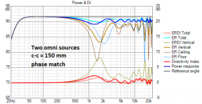
Directivity is one effective parameter, but before that we could recognize few other effects due two separate sources (assuming phase match):
- dip(s) in power response (P)
- dip(s) in early reflections (ER) due to dips in vertical plane, causing
- hump(s) in early reflection directivity index (ERDI).
Vertical nulls are usually unavoidable with multi-way (without coaxial). XDir is able to show that self-evident in addition to direction of null(s), but that's it. No value.
Simple method is to initiate c-c and XO frequency so that combination of c-c or XO frequency tries to neutralize dips in P and ER, assuming that radiators are close to omni (in half space), or lower band is beaming more. c-c is 1.2-1.4 * wave length at XO frequency.
Next level would be using some estimation for directivity e.g. rigid piston, and repeat previous sim.
Close to final level is to make prototype with almost any c-c or ~1.2 * wave length at estimated XO frequency, measure radiators separately and simulate crossing with proper tool. I'm too lazy or confident to do this phase.
Final speaker is measured with final drivers and optimized by on-axis, off-axis, LW, in-room, ER and P adjusting XO frequency, orders, phase matching with acceptable compromises. This phase is able to compensate some mistakes in c-c and XO. Null exists but sound is balanced if concept and application is otherwise okay.
Last edited:
- Home
- Loudspeakers
- Multi-Way
- What Causes Off-Axis Nulls?