Hello guys,
Am having dc offset in marantz cd6000 and i really dont have an idea what is the reason for that and how can i remove it.Probably is because i have removed the DC blocking caps that are soldered just before the rca output.
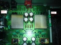
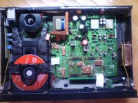
The player has audiocom superclock 2 with separate 12v psu. Several Black Gates across near the main psu, shottkey diode 11dq10,Separate toroidal for the analog part, lm4562 decoupled with BG and some other stuff that are not so important.Ive checked the power at the op amps and its the same for both of them and the resistors that are in that area but i think that the DC offset is caused from the HDAM because one capacitor near the HDAM at position 2218 is haveing 19.4mv this is for the right channel and the same position od the capacitor but on the left side of the HDAM is haveing 0.6mv the position is 2217.
The DC offset is -22 mv for the right channel and 2.8mv for the left channel.
So if anybody have any idea how can i fix this i will be very thankful 🙂
Here is a link for the service manual Categorized Schematics and Service Manuals for free download
Am having dc offset in marantz cd6000 and i really dont have an idea what is the reason for that and how can i remove it.Probably is because i have removed the DC blocking caps that are soldered just before the rca output.
The player has audiocom superclock 2 with separate 12v psu. Several Black Gates across near the main psu, shottkey diode 11dq10,Separate toroidal for the analog part, lm4562 decoupled with BG and some other stuff that are not so important.Ive checked the power at the op amps and its the same for both of them and the resistors that are in that area but i think that the DC offset is caused from the HDAM because one capacitor near the HDAM at position 2218 is haveing 19.4mv this is for the right channel and the same position od the capacitor but on the left side of the HDAM is haveing 0.6mv the position is 2217.
The DC offset is -22 mv for the right channel and 2.8mv for the left channel.
So if anybody have any idea how can i fix this i will be very thankful 🙂
Here is a link for the service manual Categorized Schematics and Service Manuals for free download
Attachments
The DC offset is obviously there because you have removed the DC blocking capacitors !!
The next question is why is this important to you ?
Do you have an amplifier without any DC blocking capacitors ???
Andy
.
The next question is why is this important to you ?
Do you have an amplifier without any DC blocking capacitors ???
Andy
.
Well Andy i was thinking the same as you say, the amplifier is Marantz pm 7000 and i didn't change anything in the Function Power Board so the capacitors by default are there.
And its important to me because i wanted to make it close to 0 Ive seen some adjustment by Trim potentiometer but i cant find any info in the pdf sheet of lm4562 how can i do it, i mean i will buy variable trims but how much resistance they should offer and most important where should i solder the 3 pins from the trim to what pin legs on the op amp?
Also one thing that bothers me most is why when i move the volume control lets say between 6 and 10 max the cones of the speakers move inside and outside is this behavior connected with the dc offset? i have adjusted the dc offset and idle-ing current of the amp before one week. Now the Dc offset in the amp is 0.7mv and 0.8mv for the left and right channel, and idling current is 19mv -+1mv for both of the channels off course it all depends of the temperature........
Alex
Unless the DC offset present at the output of the cd player is having an effect on the amplifier ( ie no dc blocking in the amplifier ), then it will have very little effect on sound.
It is possible to add adjustment pots to the opamps. This is usually done by injecting a small voltage into the -ve input via a resistor and pot ( between the -ve and +ve rails ). Remember the offsets you have now are very small and within normal values so why bother ?
Andy
.
It is possible to add adjustment pots to the opamps. This is usually done by injecting a small voltage into the -ve input via a resistor and pot ( between the -ve and +ve rails ). Remember the offsets you have now are very small and within normal values so why bother ?
Andy
.
Last edited:
Connect a battery to your speaker, what do you hear? Right.
That's what you hear when you remove the blocking cap's. Try listening with a headphone; for instance a left right comparison where you only remove the cap on one channel.
You can clearly hear strange distortions somewhat hidden in the basrespons, easily mistaken for better bas.
If there is already a input cap in the amplifier, leave them out, otherwise put a better cap back. For instance a black gate nx in super e-cap configuration or a mcp of high enough value to give you a low enough -3db (those mcp's are physicaly realy big though). 10uF is normaly enough. Do the math for -3db point as the cap forms filter with the input impedance of your amplifier.
The reason you are experiencing cone movement when you turn the volume control is (most likely, check the amplifier circuit diagram) because there's a DC coupled fet at the input to provide easy drive by the source (CD player) + easy drive of the next stage within amplifier (and potentiometer). So, RCA DC coupled to fet, impedance adjusted signal from fet stage DC coupled to potentiometer, from potentiometer you’ll find a capacitor coupling to differential stage. When you turn the wiper, you are producing very low frequency AC signal which gets amplified.... because the DC component is present on the graphyte of the pot....
Boky
Boky
U pravo si Boky🙂) prosta logika....
One of the problems was the RCA cable Monster Interlink 200 at the left channel so ive changed the RCA plugs and its much better now in therms of hum and that bzzz sound.
Now i would like to ask is where should i connect the pins from the trim to which pins of the op amp. So the trim has 3 legs 1,2 and 3, and the op amp 8.
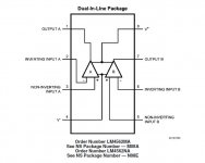
Pin 1 from the trim should be soldered to leg8 of the op amp, pin 3 from the trim to leg 4 at the op amp and pin2 from the trim to leg.... also the what kind of resistor and how many ohms should be and where i have to solder it since these are dual op amps?
Also Ive replaced the op amps at the PC sound card Creative XF-FI fatality to lm4562 and i have offset of 30.1mv left and 29,4mv right channel so i will apply the same offset adjustment like on the CD player and the card only uses one dual op amp for Front L/R channel, so i would need only one trim and resistor.
Here is a picture from LM4562 datasheet
Alex
One of the problems was the RCA cable Monster Interlink 200 at the left channel so ive changed the RCA plugs and its much better now in therms of hum and that bzzz sound.
Now i would like to ask is where should i connect the pins from the trim to which pins of the op amp. So the trim has 3 legs 1,2 and 3, and the op amp 8.
Pin 1 from the trim should be soldered to leg8 of the op amp, pin 3 from the trim to leg 4 at the op amp and pin2 from the trim to leg.... also the what kind of resistor and how many ohms should be and where i have to solder it since these are dual op amps?
Also Ive replaced the op amps at the PC sound card Creative XF-FI fatality to lm4562 and i have offset of 30.1mv left and 29,4mv right channel so i will apply the same offset adjustment like on the CD player and the card only uses one dual op amp for Front L/R channel, so i would need only one trim and resistor.
Here is a picture from LM4562 datasheet
Alex
Attachments
You are making more problems than you remove. The trimming will be affected by temperature drift of the offset. OpAmps with good DC offset will not sound good in audio.
Leave the caps in place and eventually add in parallel some polypropylene caps. Or replace them with tantalum.
Or both.
Leave the caps in place and eventually add in parallel some polypropylene caps. Or replace them with tantalum.
Or both.
Last edited:
Whatever you try - you'll still have some DC offset, unless you use DC servo to null the DC at the OP output pin....
my suggestions:
1. mundorf silver in oil (big, expensive... and really good). Wrap them completely in coper foil and ground the copper foil. Or Auri cap for cheap solution, but very good results – just pair those Auri caps with AD826AN.
2. use transformers at the DAC outputs. By far the best solution for your Vout DAC's. Simple and excellent. Check this thread for all the details you'll need:
http://www.diyaudio.com/forums/digital-line-level/137976-experience-diy-dac-254.html#post2173946
Boky
Hi Aleksandar. I've a tweaked CD6000 too and, about DC caps removal I would like to tell you some appointments:
- First of all these capacitors (2 Silmics per channel) serves for both autoprotection and not agression. I mean that if you remove them you could send (in fact you send) DC to the amplifier but you could too receive DC from amplifier what could seriously injure your CD player.
- I recommend you replacing -but not removing- them. I tried it with Auricaps getting nice results. Have in mind that these capacitors form, with 10K resistors 3247 and 3248, a per line high pass filter, what must conditiion the capacitor size.
Hope it was helpful. Regards.
Thank you Gary for your advice, i will try that in near future also because now i barley use the cd player, anyway thanks for the advice.
Regards Alex
Regards Alex
- Status
- Not open for further replies.
- Home
- Source & Line
- Digital Source
- What causes DC offset in cd 6000