Thanks Kay, credits go to TubeLab and Smoking-Amp.
In this post on the "GU50 bass amp" thread you can see the references to their idea:
450W bass amp: a sextet of GU50s with shunt¤t feedback
In this post on the "GU50 bass amp" thread you can see the references to their idea:
450W bass amp: a sextet of GU50s with shunt¤t feedback
I have one question concerning Ra: I've seen on the datasheets, and in all projects available online, that Ra for EL84 in SE is 5k2.
But it simulates better with 6k6 (it stays cleaner and harmonics above 2nd are one to two order of magnitude lower than 2nd) and I would like to know if it's something related to the model itself or it's something well known, and the Ra 5k2 that is found in every online project is just a "it is written so I apply" case?
Thanks
Appears to be very clever with that local NFB by a voltage divider that also sets - and simultaneously stabilzes - the EL84's operating point
Depending on the DCR in the OPT, there might not be much stabilization of the DC operating point.
That circuit took nearly 10 years of research and tinkering to create. The intended purpose was to run TV sweep tubes in triode mode at high plate voltages. It does that very well.
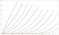
Here are the curves plotted for a 6GF5 (like a 6DQ6) sweep tube running with 150 volts on the screen. These curves were hand plotted with three analog power supplies and ran the tube well above it's published dissipation ratings, so the reading were taken quickly. This the reason for the somewhat uneven spacing of the lines.
I have a 20+ watt SE amp running that uses two stages of this circuit it work very well and has been running for about 8 months, and tested to 40 watts per channel. A new PCB design to support this is in progress. Some info is here. LTspice file is in post #48:
UNSET is coming?
In this design the plate voltage and source of the (positive) bias voltage are unregulated. With careful adjustment of the parts values these can be made to cancel such the either the tube current, or the total plate dissipation will remain constant as the line voltage changes.
All signal voltages in this amp are in phase. Care should be taken in building a multi stage amp, especially in layout and power supply decoupling to avoid instability.
Attachments
Roberto,I have one question concerning Ra: I've seen on the datasheets, and in all projects available online, that Ra for EL84 in SE is 5k2.
But it simulates better with 6k6 (it stays cleaner and harmonics above 2nd are one to two order of magnitude lower than 2nd) and I would like to know if it's something related to the model itself or it's something well known, and the Ra 5k2 that is found in every online project is just a "it is written so I apply" case?
Thanks
don't forget the goal the tube manufacturers (Mullard in this case) had when publishing their sheets: First one was to squeeze as much of power as possible
out of the specific tube. For EL84 this means: Pdiss max = 12 watts, divided by 250 Vplate gives Iplate = 48mA. Rplate for maximum output power for a pentode means Vplate/Iplate = 250 V/48 mA = 5200 Ω, this at THD = 10 %.
Best regards!
LTspice file is in post #48:
UNSET is coming?
Thanks Tubelab! I will try to dig it more with all your hints.
I hope you don't mind if I'll ask you something more "on the way".
Thanks Kay, so all projects that can be found online are just "copy-paste" of the datasheet, without further research on it. As you know I'm not EE nor I've so much experience in this field, but Ra=6k6 performance "on paper" seems better to me.Roberto,
don't forget the goal the tube manufacturers (Mullard in this case) had when publishing their sheets: First one was to squeeze as much of power as possible
out of the specific tube.
I have one question concerning Ra: I've seen on the datasheets, and in all projects available online, that Ra for EL84 in SE is 5k2.
But it simulates better with 6k6 (it stays cleaner and harmonics above 2nd are one to two order of magnitude lower than 2nd) and I would like to know if it's something related to the model itself or it's something well known, and the Ra 5k2 that is found in every online project is just a "it is written so I apply" case?
Thanks
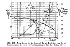
A single ended pentode EL84 should have rising 3rd harmonics and dropping 2nd above 5kohm, as in the attached diagram for the EL41 which is the forerunner tube from which the EL84 was derived. At 5.2k combined 2nd+3rd distortion should be minimal and output power max at the same time. I quickly checked this with a single tube and my sim confirm the curves from the diagram. The problem might be your tube models (I am using Ayumi's) or the rest of your circuit, which I did not simulate.
By the way, my Philips data sheet has tables for 4.5kohm, 5.2kohm and 7kohm ...
Attachments
Last edited:
- Home
- Amplifiers
- Tubes / Valves
- What can I do with them? 4x 1L4, 1x 6AQ5, 3x 6BQ5, 1x 6SN7