Cleaned the contacts on the relay, they wernt too bad, but worth a try. I also tested the nearby 47 micro farad cap which is fine it seems. I cant test it until my new alps pot arrives.
Cheers
Chris
Cheers
Chris
Thanks guys 🙂
Yes they are fine, but replacing them wont hurt as a preventative measure.
They were in there, working well for decades. And they are still good. That's a clear sign of robustness, so don't replace them. Also, as far as I can tell from the picture, the discoloration is not on the diodes, but on the PCB.
the only heat stress I can see is the PCB discoloring? this maybe a "designed in feature", (measure the bias thru the diodes and compare the power ratings from the data sheet.) its not uncommon to see esp. for a grouping of heat sources.
replacing all the zeners, even if it goes right, wont change a thing. . and parts just don't go bad in mass groups without reason, so finding the reason becomes key. BTW I'm not a fan of shotgun part replacement procedures
replacing all the zeners, even if it goes right, wont change a thing. . and parts just don't go bad in mass groups without reason, so finding the reason becomes key. BTW I'm not a fan of shotgun part replacement procedures
Last edited:
The diodes in the middle of the line have cracks in them and are crumbly at the ends, I will keep looking for the fault but they will get swapped out in the refurb to ensure further decades of happy service.
I took the volume pot apart even though I have a new one on the way and with thin strip of 1200 grade I cleaned the swiper contacts then soldered it back in. This got rid of crackle, but not the hum, but it is something close or related. The hum even when the volume pot was in its low hum position was louder than normal. I tapped the volume knob hardish and the hum reduced significantly, back to its normal level so there is a dodgy connection somewhere, but not obvious I have been over the board with with high magnification and all looks good. I wonder if the relay is not throwing in correctly or something?
Either that or one of the valves, any ideas guys? I still cant understand why the resistance of the volume setting ie position of the volume knob is dictating the hum level either.
Cheers
Chris
sometimes the force applied to the knob causes the PCB to flex in other spots, I usually just hit the connections that go off board and that are connected to larger objects / assemblies like all the potentiometers and RCAs.
There's only 3 possibilities: open/working properly/shorted, any and all can easily be tested without even desoldering just by reading voltage drop across it.either the diodes which are not well
It isn't as if "they are X years old and are worn" , they either work properly or are dead.
Replacing them is not preventive maintenance by any means, because there is no wear mechanism.
There's only 3 possibilities: open/working properly/shorted, any and all can easily be tested without even desoldering just by reading voltage drop across it.
It isn't as if "they are X years old and are worn" , they either work properly or are dead.
Replacing them is not preventive maintenance by any means, because there is no wear mechanism.
I know that diodes either work or they dont and these work, but when they are cracked and going powdery at the ends they are not perfect either. Would a brand new good quality replacement last longer than a cracked crumbling diode? Of course it will. When and if the cracked crumbling diode fails will the amp go quiet with no other problems or will the failed diode take out another more expensive component? Even worse send a destructive tone out to my ATC scm 100's. I am not going to take the chance it cost me like three buck for a big bag of quality diodes and it will take me maybe 10 minutes to solder them in no risk and peace of mind.
Chris
sometimes the force applied to the knob causes the PCB to flex in other spots, I usually just hit the connections that go off board and that are connected to larger objects / assemblies like all the potentiometers and RCAs.
I thought the same, but the board that the pot is connected to is a long thin board with not much on it, I will have another look though. I wonder though if the shock of tapping the volume pot hard is nugging something on the main board, or maybe that relay at the rear of the amp? Next time I will try gently tapping the top of the relay directly and see what that does.
Cheers
Chris
I know that diodes either work or they dont and these work, but when they are cracked and going powdery at the ends they are not perfect either.
A 1N5257B drops 33V at 3.8mA
Your schematic reads 380Vdc on the output.
Means voltage drop across each zener is at least 1V less.
Means nominal zener current is a lot lower than 3.8mA, according the graph of the linked datasheet ~2mA.
2mA times 32V (33V -1V) makes 64mW dissipation, ~1/8th of the nominal max 500mW dissipation.
Means you better refresh the entire 12 for new ones.
(some look like parts of one end of the zener body cracked off)
Ok I am getting somewhere I found another fault, not yet quite sure what it means though, but I am guessing it is all related. The balance control does nothing at all, I then tried unplugging one channel and sure enough one channel goes off so stereo operation is working. I then tried selecting on the channel selector right, reverse, left stereo and right again there was no difference at all so the controls for balance and channel switching are doing nothing. The fault I am guessing is on the thin front board with the volume, balance and channel selector on it, this has to be the source of the hum, I hope so anyway. I need to go and do a bit of work, but I will have another look later any thoughts guys what might be at fault?
Cheers
Chris
Cheers
Chris
If you ask me, Q1 is shot and turned short circuit, which blew all zeners.(reason for the board to discolor)
The zeners handle 500mW max, they'll blow with less than 15mA current through them (see figure 3 of the datasheet)
If nominal zener current is about 2mA, the resistor R3 above Q1 will likely be in the order of 300 to 332 ohm (depending on the series)
Even if R3 is a 0.25W type, it can easily survive a current of 15mA and more.
In that case, you'd still have an output voltage for the valves of the preamp, but both channels will buzz.
I tested the zeners in circuit and they seemed good. I might desolder a couple and test them properly then. Thanks much appreciated 🙂If you ask me, Q1 is shot and turned short circuit, which blew all zeners.(reason for the board to discolor)
The zeners handle 500mW max, they'll blow with less than 15mA current through them (see figure 3 of the datasheet)
If nominal zener current is about 2mA, the resistor R3 above Q1 will likely be in the order of 300 to 332 ohm (depending on the series)
Even if R3 is a 0.25W type, it can easily survive a current of 15mA and more.
In that case, you'd still have an output voltage for the valves of the preamp, but both channels will buzz.
Cheers
Chris
Just desoldered them and checked them properly they are fine. There was a suspect dry joint which I fixed but still hum, oh well it was worth a try 🙂
Thanks very much for the input 🙂
Cheers
Chris
Thanks very much for the input 🙂
Cheers
Chris
Makes me wonder what made the board change color that much.
For the short-lead mounted ones, temp difference to expect according to datasheets is less than 20C above ambient for a zener dissipation of 65mW.
For the short-lead mounted ones, temp difference to expect according to datasheets is less than 20C above ambient for a zener dissipation of 65mW.
Makes me wonder what made the board change color that much.
For the short-lead mounted ones, temp difference to expect according to datasheets is less than 20C above ambient for a zener dissipation of 65mW.
Yes that is very strange, on the other side of the board the burning was worse, thick carbon they must have been way over 20C above ambient..
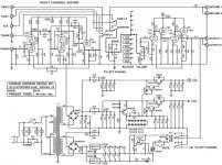
I have a few better diagrams with actual components on them but they wont upload for some reason it keeps telling me invalid file. What do you think it is worth checking first? I was thinking apart valves check the silicon ie other diodes, q1-5 and bridges ect. Where do you think the fault is most likely to be?
Cheers
Chris
Single sided PCB, the heat is dumped to the pads on the solder side.Yes that is very strange, on the other side of the board the burning was worse, thick carbon they must have been way over 20C above ambient......
The power rating goes down when hot components are packed together like this ( why you should use lead spacers to lift them away from the board)
The fixing screw and washer at the top of the photo are very rusty, this board has been kept damp at some point
It's a cracked plastic washer, and the parts don't look that rusty for a three decade old valve preamp.
(back in the old days, a way to keep zener diodes cooled was by adding a thermal dissipation pad on the mounting side)
Considering it's age, single run-out excuse I can think of is that it has already been repaired once, after it failed as a result of overheating under a quarter inch of collected dirt and dust.
(amusing, the schematic of the Premier 3 revision has three 5257's exchanged by 27V types. 332 ohm for R3, 2mA zener current, JS dissipation)
Attachments
Last edited:
What do you mean 5257 exchanged for 27v types?It's a cracked plastic washer, and the parts don't look that rusty for a three decade old valve preamp.
(back in the old days, a way to keep zener diodes cooled was by adding a thermal dissipation pad on the mounting side)
Considering it's age, single run-out excuse I can think of is that it has already been repaired once, after it failed as a result of overheating under a quarter inch of collected dirt and dust.
(amusing, the schematic of the Premier 3 revision has three 5257's exchanged by 27V types. 332 ohm for R3, 2mA zener current, JS dissipation)
Cheers
Chris
he's noting the zener string is composed of 2 different part types in an attempt to nail the final voltage.What do you mean 5257 exchanged for 27v types?
Cheers
Chris
- Status
- Not open for further replies.
- Home
- Design & Build
- Parts
- What are these components