Posted this in 6L6 build guide, but probably be better just asked in own thread.
In his firing up instructions, after doing the front end and moving to output settings, it is noted to bias up the outputs to .25 volt, but later mentions to then go to full 100% bias. Could someone tell me what that is? I am ready to do so...help!😱
Thank you for any help, I want to hear this thing!
Russellc
show me exact schm of OS you're using
Sorry, it is the complementary output stage from the store...although the store schematic shows 6 pairs, and single set of Store boards only has 3 pairs. It is exactly like the BA-3 in 6L6s build thread.
http://www.diyaudio.com/forums/pass-labs/258301-ba-3-amplifier-illustrated-build-guide.html
Russellc
for 3 deep use 0R47 source resistors
say that 500mA is lowest you need to go per vertical pair
if heatsink is sufficient (palm rule) go higher
say that 500mA is lowest you need to go per vertical pair
if heatsink is sufficient (palm rule) go higher
well, I used the Store BOM so there are 1 ohm source resistors. I know the figure you gave would now likely be different. 500 per pair, 3 pairs, so 1500 mA? (heat sink is 5U store chassis) 1500 Ma = 1.5 amps then? Well except for different figure for 1 R source resistors? What would this equate to in volts across the source resistors? Asked another way how many mA would there be with .25 volts across 1 ohm source resistor? I doubt these sinks are going to allow much higher bias....
Russellc
Russellc
Last edited:
I read 6L6s build thread many times, read Papas piece on it, all not just "meat" with no answer. Going back through BA-3 sticky...doesnt look like its getting fired up (well,beyond warm up at .25 volt across 1R source resistor anyway) this evening. I understand this is a "Burning Amp" and all but dont want to experience it beyond figuratively if possible!😀
Russellc
Russellc
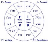
three R's are pretty important , everywhere ..... 
so - if you print attached image on A4 , you'll grasp it one day .......
I=U/R .......... U=RI .......... R=U/I
1A through 1R will give 1V across resistor terminals
so 0V25 across 1R is 250mA through
use 0R47 source resistors (explained why in 6L6's first post )
if you have enough 1R ones , just double (parallel) additional ones across existing ones on pcb
recheck bias afterwards ...... or - even better - back with bias voltage prior to powering up , then set again
Attachments
three R's are pretty important , everywhere .....
so - if you print attached image on A4 , you'll grasp it one day .......
I=U/R .......... U=RI .......... R=U/I
1A through 1R will give 1V across resistor terminals
so 0V25 across 1R is 250mA through
use 0R47 source resistors (explained why in 6L6's first post )
if you have enough 1R ones , just double (parallel) additional ones across existing ones on pcb
recheck bias afterwards ...... or - even better - back with bias voltage prior to powering up , then set again
Yes I see where he says it will give more power and assumes mosfets are closely matched. This set came from Tech-diy back when they were supplying parts and I dont know how tightly they are matched. I dont need the extra power, so really dont want to alter them and risk literal "Burning Amp" plus I see 6L6 left in 1R units, I dont need the extra power.......On the other hand, I do have enough 1R resistors to do that.
I will definitely take your advice on powering up. I will make sure first, but I think with my 1R resistors, 1.5 volts is max....not going to try until I am sure!
Last edited:
The amp is biased up to .25 volt, DC offset adjusted to little or nothing. Going to let it cook a little while at this low bias, then measure temps and juice it up a little more.
Conversion of mA to volts is easy, especially if your source resistor is 0ne! or I guess you can have google perform:
http://www.convertunits.com/from/mA/to/volt/ohm
Still dont feel comfortable just going to 1.5 volts without more info. Thus, will go up slowly taking temps off mosfet and heat sink and see where I get. I would really like to have it making music tonight!
Russellc
Last edited:
Heat sink just starting to warm a tiny bit....offset holding, bias drifted up just a touch, .268 volt. Very little difference so far between mosfet and heat sink: Mosfet = 38+C, Heatsink 38+C...few more mins and we will go up a little.
Russellc
Russellc
Last edited:
Hi Russellc,
I think the BA2 output stage as drawn in Mr Pass' article is biased at 1.5A
(0.25 V across 1 ohm source resistors and 6 pairs of transistors).
If you're running 3 pairs with the same 0.25 V across 1 ohm source resistors
then you should have 0.75A bias. I think transitions into class B at about
9W RMS into 8 ohms.
What rail are you running at? If you're using +/-24V then the total dissipation
is about 36W.
Increasing to 0.5V across the 1 ohm resistors should give you 1.5A bias
and a much higher class A value.
Cheers,
Dennis
Set it up to .30 volt, Heatsink AND mosfets 42+C on average. This amp is very stable in terms of Bias and offset.
Russellc
Russellc
Hi Russellc,
I think the BA2 output stage as drawn in Mr Pass' article is biased at 1.5A
(0.25 V across 1 ohm source resistors and 6 pairs of transistors).
If you're running 3 pairs with the same 0.25 V across 1 ohm source resistors
then you should have 0.75A bias. I think transitions into class B at about
9W RMS into 8 ohms.
What rail are you running at? If you're using +/-24V then the total dissipation
is about 36W.
Increasing to 0.5V across the 1 ohm resistors should give you 1.5A bias
and a much higher class A value.
Cheers,
Dennis
The .25 was just a warm up amount to start with. As I said above just now, I am slowly dialing it up and watching the temps. The transformer is a 24 + 24 volt 1000VA unit, unloaded rails were 34 volts. I know my F-5 "sagged" a little once loaded...I was under the impression that A higher VA transformer would not sag as much, leaving me a little concerned about being so close to the 40 volt break down of the Jfets, but AndrewT explained I was mistaken and the voltage would be the same, so I suppose it sagged a little too, giving a little more margin. I will measure it before I shut it down.
6L6 calculated in his build thread for the BA-3 amp that 32 volt rails should yield somewhere around 40 watts output, I dont know if that was class A, but I assumed it was as it also showed 25 watts with the more typical 24 volt rails, like my F-5 had.
Any idea how high I need to take this thing to make music? Based on Zen Mods info I (not ZM) calculated that maximum bias would be 1.5 volts across the source resistors, but I do not trust my math....this why I am slowly going up and measuring heatsink and mosfet temps as I go up. Hopefully soon I will learn for sure what "full" or 100% bias is, although I dont know what the U5 Store chassis and heatsinks will allow. Apparently it is a big mystery! It just wasnt mentioned in the build thread 6L6 did. I'm sure I will hear from him soon, I hope.
Given what I have seen so far, I cant imagine 1.5 volts across the resistors, may be .5 is the max?
Russellc
Last edited:
At .30 volts, the mosfets are averaging 45 C or so, heat sinks about the same.
my F-5 mosfets are running about 54C, sinks about 37, there is a ceiling fan running in there...
Russellc
my F-5 mosfets are running about 54C, sinks about 37, there is a ceiling fan running in there...
Russellc
In the F-5 thread Nelson says of these IRF units 55 on the heatsink, 65-70 on the mosfet case and they "seem to run forever" so I am guessing this will be the stopping point for now.
Up to .380 now, very warm but mosfets havent hit 50c yet lets see...
Oh, and loaded rails are just under 32 volts DC..of course AndrewT was right on that, I feel a little better!
Reading the BA-2 material suggested above, like Zen Mod said, they also recommend smaller source resistors with only 3 pairs. It also appears there is more bias margin as well, less heat from less outputs.
Russellc
Last edited:
Went up to .475, forgot I only had 2.5 amp fast blo, and they blew. I could sneak up on them with the variac for initial fire up, but I guess that's all they could take. oh well. I will have to get more of these small size fuses the IEC on this thing takes.
Russellc
Russellc
whatever you do , don't go above 55C on heatsink
though , maybe you don't need more reading , but thinking certainly do - 1V5 across 1R means 1A5 through each vertical par , with 38V rail that means 57VA (57W) which is ..... plenty
luckily , you'll hit 55C at heatsink way before
biasing in Papamps is easy - crank it until you hit any of these :
-35W per mosfet,
-55C at heatsink (taking care of summer T amb. )
whatever you do , don't go above 55C on heatsink
though , maybe you don't need more reading , but thinking certainly do - 1V5 across 1R means 1A5 through each vertical par , with 38V rail that means 57VA (57W) which is ..... plenty
luckily , you'll hit 55C at heatsink way before
biasing in Papamps is easy - crank it until you hit any of these :
-35W per mosfet,
-55C at heatsink (taking care of summer T amb. )
Mosfet body just getting to 50C, heatsink still mid 40s...only had 2.5 fast blos in this small size. They cooked! Searching, but I think all others are large size😡 Frankly, I didnt think they would last this long
Russellc
OK, back at it with new fuses. Bias at .50 volt mosfets heating up. .480 didnt have them to 50C yet, I think .500 will. Heatsink 47C at hottest spot I can find, easily grabable. Cook, cook cook.😉
Russellc
Russellc
Last edited:
Mosfets highest temp (some a little lower) is at 48C, Hottest point on sink is the same. Waiting to see if it will creep to 50C, then I'm giving it a go! Bias is .509 and .511. Seems odd the sink and the Mosfets are so close in temp. This is not the case with my F-5, the sinks always run cooler, both amps are using keratherm pads. The F-5 sinks are massive. These sinks wont take much more, I am unwilling to push mosfets past 55C....for now anyway.
Russellc
Russellc
Last edited:
- Status
- Not open for further replies.
- Home
- Amplifiers
- Pass Labs
- What are the outputs full or 100% bias on BA-3 amp?