I usually see terminal 1 & 4 connected to a pot with the center tap to a resistor at the cathode.
How do you know what voltage to apply to terminal 1 & 4? Should the voltage be an AC or DC source?
How do you know how to adjust the pot? Should the pot be at the center point?
How do you know what voltage to apply to terminal 1 & 4? Should the voltage be an AC or DC source?
How do you know how to adjust the pot? Should the pot be at the center point?
Sounds like the filament. You need 5VAC at some amps, although some argue DC is better/worse (with absurd logic of course, but we're talking the 300B here -- these things trancend logic, as jewelry to a woman).
The pot nulls the AC voltage so it isn't amplified (since a voltage at the cathode looks the same as a voltage at the grid). As such, you want to adjust the pot (by meter or by ear) to yield the lowest hum in the output. A pot is unnecessary with DC heating.
The resistor to ground sets bias by the current through it, which since it also passes through the tube, is a very stable source of this bias. It provides a positive bias, but since the grid is grounded (through an interstage transformer, grid choke or grid leak resistor), appears negative to the tube and thus sets it in a comfortable position.
Tim
Pins 1 and 4 are indeed the filament of the 300B (As Tim has said). It needs 5VDC at 1.2A or 5V RMS at 1.2A RMS to operate correctly. The filament must be heated so it can create a cloud of electrons around it through thermionic emission. These electrons are attracted to the anode (which is positive with respect to the filament). The grid is negative with respect to the filament (usually), so it does not attract electrons to it. The grid voltage thus can exercise control over the current through the valve (more negative -> less current, less negative -> more current). That was a very simple explanation of the basics of how thermionic valves operate, from the 300B to the little 5702.
What Tim means, is that when you connect a resistance between the centre-tap of the filament transformer, or the hum pot wiper, and ground, a voltage must develop across that resistance when current flows through the resistor: Ohm's law, V=IR. Thus, the filament (acting as the cathode) will be positive with respect to ground. Yet, the grid is at ground potential (since it is grounded through the grid resistor, or choke, or interstage transformer, or whatever). Therefore, the grid is negative with respect to the filament. The size of this resistance between the filament and ground determines how negative the grid becomes with respect to the cathode, and thus determines the standing current through the valve.
I'm not sure if this answers your question a little more clearly (actually I'm not entirely sure what the question was), but I hope this helps. Perhaps something like the "Grounded Cathode Amplifier" article at the TubeCad Journal may be more helpful.
It's much easier to understand something if you've got something in front of you, like a schematic of a 300B amp or something. If you're still confused, post something like that, and I'll try (or anyone else for that matter) to explain what the components do, and how they affect the operation of the valve.
andy2 said:I would like to add that what are the effects of biasing terminal 1 & 4?
How does it affect the operating condition of the tubes?
Does bias affect the standing current of the tube?
What Tim means, is that when you connect a resistance between the centre-tap of the filament transformer, or the hum pot wiper, and ground, a voltage must develop across that resistance when current flows through the resistor: Ohm's law, V=IR. Thus, the filament (acting as the cathode) will be positive with respect to ground. Yet, the grid is at ground potential (since it is grounded through the grid resistor, or choke, or interstage transformer, or whatever). Therefore, the grid is negative with respect to the filament. The size of this resistance between the filament and ground determines how negative the grid becomes with respect to the cathode, and thus determines the standing current through the valve.
I'm not sure if this answers your question a little more clearly (actually I'm not entirely sure what the question was), but I hope this helps. Perhaps something like the "Grounded Cathode Amplifier" article at the TubeCad Journal may be more helpful.
It's much easier to understand something if you've got something in front of you, like a schematic of a 300B amp or something. If you're still confused, post something like that, and I'll try (or anyone else for that matter) to explain what the components do, and how they affect the operation of the valve.
It's much easier to understand something if you've got something in front of you, like a schematic of a 300B amp or something. If you're still confused, post something like that, and I'll try (or anyone else for that matter) to explain what the components do, and how they affect the operation of the valve.
OK-- if this is considered hijacking the thread, then please say so, but I think this insane offer to describe the workings of a tube circuit is an opportunity I cannot afford to waste.
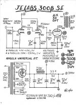
I've attached the schematic for the JE Labs 300B amplifier from Angela, which I think is a good example 300B circuit. Its reasonably simple (reasonably) and probably offers a look at a basic amplifier topology for a variety of SET designs.
Hopefully I got all the lingo right--- we're talkin' noobie here.
Let's look at the main circuit (i.e., not the power supply, right now). It seems (based on my VERY limited understanding of circuits) that the 100K pot is to vary the amount of signal passed to the grid of the driver tube (6SN7). The first half of the triode is cathode-grounded though a 470R resistor.
I imagine that Ohm's Law is used to determine the resistor value to properly reference the cathode to ground, but could someone explain this in simple terms (remember, I'm a stupid newbie)? Why couldn't the cathode by tied to ground using any old resistor (I think I sort of know why, but I want to actually, really know why), or simply be grounded without any resistor at all?
This is likely to be the beginning of quite a few questions, so please stop me, andy2, if you think I'm hijacking this. I just thought that since your initial questions were similar to my own that we could both benefit from the explanation of this circuit.
Also, feel free to take us through the mind of the electrons as they pass though the various components here. I really have a very limited knowledge, so some kind of puppet show-style explanation would NOT be considered patronizing.
Hey-- how about a stream-of-conciousness, one-act play? Take me to the SOUL of the electron. I want to feel its reaction to resistance... its malaise over capacitance...
OK, too much Kofi. You're raising too many eyebrows.
Seriously, any help explaining this (or any) tube circuit would be much appreciated!
Thanks,
Kofi
Attachments
andy2 said:OK.
I see that those terminals are connected to pin 7 and 8 of the 6SN7 pair.
Why don't you need the same pot used in the 300B for the 6SN7 for the filament heater?
Why is it that you can connect them directly to 7 and 8?
You've missed something that the 300B is famous for (and part of the reason why I think it's a bit of a pain...). It doesn't have a real cathode, i.e. it is directly heated (you have to have heard DHT: 'directly heated triode' before in marketing material somewhere?)
In the 6SN7, the part of the valve which emits the electrons is the cathode, a metal sleeve coated with alkali metal oxides, which is heated by a thin tungsten wire inside it, not surprisingly called the heater. There is insulation between the heater and the cathode, so they are electrically separate (not completetly true, the insulation isn't perfect). Thus, you can apply a voltage to the heater of the 6SN7, heating the cathode and allowing it to emit electons, and use a seperate components between cathode to ground for biasing. (One of the pins is connected to the metal sleeve of the cathode).
In the case of the 300B, this valve has a FILAMENT, like a light bulb. There is no separeate heater and cathode. The filament is like the heater (a thin tungsten wire), except the oxide coating in this case is applied directly to the tungsten wire instead of to a metal sleeve surrounding it. All the hum pots and what-not are circuitry to create a "virtual cathode", i.e. to emulate the function of the cathode in an indirectly heated valve.
I have a few pictures which might explain the difference between directly heated valves and indirectly heated valves better (from an old RCA valve manual from the late 1920s or early 1930s). When I find it, I'll post it.
Kofi Annan said:Also, feel free to take us through the mind of the electrons as they pass though the various components here. I really have a very limited knowledge, so some kind of puppet show-style explanation would NOT be considered patronizing.
Hey-- how about a stream-of-conciousness, one-act play? Take me to the SOUL of the electron. I want to feel its reaction to resistance... its malaise over capacitance...
LOL
 Ok, SET isn't too complicated, I'll give it a go. But first, congratulations for getting into valves - I've seen a few posts of yours in the SSatanic forums
  (ok, I stole the SSatanic bit from Tim)
 Now, the answer to your first question.
Kofi Annan said:I imagine that Ohm's Law is used to determine the resistor value to properly reference the cathode to ground, but could someone explain this in simple terms (remember, I'm a stupid newbie)? Why couldn't the cathode by tied to ground using any old resistor (I think I sort of know why, but I want to actually, really know why), or simply be grounded without any resistor at all?
The resistor value (470 ohms) was chosen to set the bias for the input valve (the first half of the 6SN7 - this valve has two triodes in one envelope). The current through the valve (this is a triode in class *1, so the cathode current is equal to the anode current, and the grid current is ideally zero) is 4.2mA. This current must pass through the cathode resistor, and through Ohm's Law, V=IR=4.2mA x 0.47K = 2V. This is the voltage at the cathode with respect to ground.
Now, the grid of the input valve is grounded through the volume pot. Why? I hear you ask. Ok, for the moment all I'm talking about is DC operating point. So, since there is no grid current (Class *1), no DC voltage appears across the part of the pot between the grid and ground. Thus, the grid is at ground potential. But hang on, I just said that the cathode was at +2V with respect to ground. Now some complicated mathematics, so bear with me. The grid is at 0V (it's grounded) and the cathode is at +2V. So the grid voltage with respect to the cathode is the grid voltage minus the cathode voltage, i.e. 0V - 2V = -2V. Phew, glad that's over.
We've determined that the grid is 2V more NEGATIVE than the cathode. For a reason that will be clear soon, this, and the plate voltage determines the standing current (bias) through the valve. (The more negative the grid with respect to the cathode, the less standing current)
Lets say we decrease the cathode resistor value. Less voltage will be developed across it, and thus the grid will be less negative with respect to the cathode. This results in more current being drawn.
Ok, lets make the cathode resistor a little larger. More voltage is developed across it, and the grid becomes more negative with respect to the cathode. This results in less current being drawn. So, you can't just use any old resistor without changing the bias through the valve and DC operating point.
The designer of the circuit chose 470 ohms to set the DC operating point of the valve. To be truthful, you need a little more than Ohm's law alone to determine it (you need the anode characterisics of the valve - basically a graph of anode current against anode voltage for various grid voltages, and need to know how to draw the loadline).
Hmm, here is where I realise this post is already quite long, and might take a break before trying to explain the rest of it...
Andy,
Ok, this is the image I promised from the RCA manual. It's an excerpt from page 2 of the R10 manual, which I'm glad to say is available online in complete form as a PDF from here, thanks to Gary Kaufman. It's rather large at 8MB but contains a good explanation of the operation of thermionic valves (much better than I can manage) between pages 1 and 6. It also contains the data on all RCA receiving types of the era (basically any two-digit valve number i.e. 45)
I recommend that Kofi gives this a read as well (pages 1 to 6). It explains the basic operation of valves much better than I can.
If you don't want to download the entire 8MB, I have linked each page below (thanks to Tim Reese):
Page 1
Page 2
Page 3
Page 4
Page 5
Page 6
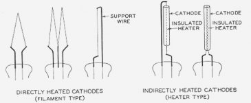
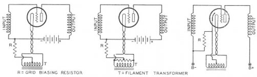
This might also be useful. It's a diagram from page 19 of the same manual showing how DH (directly heated) and IDH (indirectly heated) triodes are wired to light up their filaments/heaters, and where the self-bias resistor/cathode resistor is positioned.
Attachments
what is the purpose of the 3.3K resistor
Together with the capacitor after it, it forms an RC filter. I.e..reduces ripple...or provides better DC....
one could also have used a choke ...but the resistor has a dual function really...it also reduces the voltage to a level better suited for the driver tube..(a choke has lower dcr (resistance) and therefore drops less voltage)...and is also more expensive than a resistor.
Now, the answer to your first question.
YEAH!!! Thanks for doing this. You don't know how much this helps.
The current through the valve... is 4.2mA.
How did you determine this? Is it based on the specifications in the schematic, through the data sheet for the tube or otherwise?
The designer of the circuit chose 470 ohms to set the DC operating point of the valve. To be truthful, you need a little more than Ohm's law alone to determine it (you need the anode characterisics of the valve - basically a graph of anode current against anode voltage for various grid voltages, and need to know how to draw the loadline).
You know... I think I actually get this, kinda.
In looking at the plate curves on the 6SN7 (actually, 6SN7GT) data sheet, at about 90V (which is the plate voltage, according to the schematic) and -2V grid voltage (that's Ec, right?), the plate current is about 4.2mA. So, at least I can tie back to the data sheet, which is comforting.
Now, I know that there's a reason that specific bias points are chosen, which probably has something to do with ensuring that the tube's operation does not exceed its capabilities, but I'm not sure why one point would be chosen over another.
And now, another generic and asenine question.
On the other half of the triode, there's 98V at the cathode (according to the schematic) and there's a cathode resistor that is bypassed with a capactor. Is this a bias setting for the other half of the triode? If so, why is the capacitor there?
Thanks so much for all your help.
Kofi
Kofi Annan said:How did you determine this? Is it based on the specifications in the schematic, through the data sheet for the tube or otherwise?
Easy. I cheated.
Ohm's law states V=IR, hence I = V/R
Look at the resistor at the cathode.
So since the cathode current equals the anode current, the anode current is 2V/470 ohms = 4.255mA (ok, I actually should have said 4.3mA, not 4.2mA, but who cares about 100uA)
OK, so here goes, second time lucky.
First, a bit of terminology. Eb and Ib are plate voltage and current respectively, while Ec and Ic are grid voltag and current respectively. Plate and anode are the same thing (I jump between them a little)
There are a few maximum ratings for valves which you must make note of such as max plate voltage, max cathode current, max plate dissipation, max grid dissipation etc. For small-signal amplification, very rarely do these maxima get approached, so often the valves last for a long time (perhaps many decades).
What the designer would have (should have?) looked for in an operating point is a part of the anode characteristics where the lines are evenly spaced and parallel. This implies low distortion. The 6SN7 is particularly good in this regard, especially at currents greater than 8mA.
First, a bit of terminology. Eb and Ib are plate voltage and current respectively, while Ec and Ic are grid voltag and current respectively. Plate and anode are the same thing (I jump between them a little)
Originally posted by Kofi Annan
Now, I know that there's a reason that specific bias points are chosen, which probably has something to do with ensuring that the tube's operation does not exceed its capabilities, but I'm not sure why one point would be chosen over another.
There are a few maximum ratings for valves which you must make note of such as max plate voltage, max cathode current, max plate dissipation, max grid dissipation etc. For small-signal amplification, very rarely do these maxima get approached, so often the valves last for a long time (perhaps many decades).
What the designer would have (should have?) looked for in an operating point is a part of the anode characteristics where the lines are evenly spaced and parallel. This implies low distortion. The 6SN7 is particularly good in this regard, especially at currents greater than 8mA.
- Status
- This old topic is closed. If you want to reopen this topic, contact a moderator using the "Report Post" button.
- Home
- Amplifiers
- Tubes / Valves
- What are terminal 1 & 4 of 300B tube