A bridge of diodes when disconnected from the transformer and from the PSU will have the four diodes in a "ring". Placing a voltage source (diode test) across one diode will show a diode voltage in one direction and a high voltage in the other direction.
A shorted diode would would show a very low voltage reading and an open diode would show a very high voltage in both directions.
A shorted diode would would show a very low voltage reading and an open diode would show a very high voltage in both directions.
i am newbie...i have intex 2.1 and i want to build only subwoofer circuit only bass/...i have onida ky thunder speaker ...so please give easiest and best diagram
So you have the fabulous Onida 29" TV with 1200W power amplifier driving 4 wall shaking 6x4" woofers mounted in its plastic cabinet and you want to improve on that?i am newbie...i have intex 2.1 and i want to build only subwoofer circuit only bass/...i have onida ky thunder speaker ...so please give easiest and best diagram
An externally hosted image should be here but it was not working when we last tested it.
Sorry but we doubt we are up to the task, given that Technological Marvel specs.

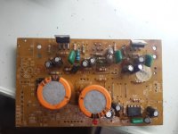
well, in the middle of the PCB there's the C5 saying : From Volume
So that's where the left & right channel go ( the satellites)
On one side of the PCB there's the CN(8?) labelled as Bass : In. Out. Ground
I expect a single potentiometer should be positioned in there
Then, following the path of the big supply capacitors then the rectifier diodes ....
So that's where the left & right channel go ( the satellites)
On one side of the PCB there's the CN(8?) labelled as Bass : In. Out. Ground
I expect a single potentiometer should be positioned in there
Then, following the path of the big supply capacitors then the rectifier diodes ....
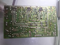
Follow the path from pin 8
pin# 4 is Ground, as all op-Amps ( negative)
Output from op-amp is pin 1 or 7. In this case pins 6-7 are tied together, and output is followed by the volume pot (missing) via C37
pin# 4 is Ground, as all op-Amps ( negative)
Output from op-amp is pin 1 or 7. In this case pins 6-7 are tied together, and output is followed by the volume pot (missing) via C37
Last edited:
- Status
- Not open for further replies.
- Home
- Amplifiers
- Chip Amps
- What are best ICs to replace for 2.1 Computer speaker Subwoofer system.