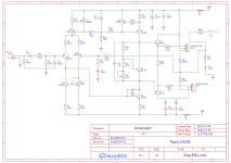
Connect two pins of VR1 together, the slider and one end. R17+Vr1= 220 to 420 Ohms, actually about R16/(4-1)=333 so that Vce Q8 = 4x diode drops. You want to make it impossible for Vce Q8 to exceed about 5 or 6 Volts, which is what would happen if the pot shorted Q8 base to emitter. The divider R16 and (R17+VR1) multiply the B-E diode drop of Q8, which should match the total BE drops of Q10, Q11, Q12, Q13, ie 4x. So R17+VR1 should be (R16/3)= more than R16/4 and less than R16/2.

I think I got it:
VR1 after calibration should be set about 0.433Ω?
VR1 sets the bias point of not only Q8 but also Q12 and Q13. It is responsible for adjusting the base current of Q8, which, in turn, affects the bias current flowing through the output transistors (Q12 and Q13). By adjusting VR1, you can precisely control the bias current of the entire output stage?
What about the rest of the circuit? Anything worth mentioning?
Many thanks
Is this good for the job:
https://www.lcsc.com/mobile/product...entiometers_BOURNS-3362P-1-201LF_C124581.html
Or should I find a better option?
https://www.lcsc.com/mobile/product...entiometers_BOURNS-3362P-1-201LF_C124581.html
Or should I find a better option?
- Home
- Design & Build
- Software Tools
- What am I doing wrong?