I apologise. I drew that diagram based on the good speaker with the intact 50 ohm l-pad I did it rather hurriedly this morning as we are under a heavy snow here and have been attending to other things around the house.
I will look at it again later tonight and see if I haven't misconstrued this somehow. I swear I'm not a thicko! 😉
I will look at it again later tonight and see if I haven't misconstrued this somehow. I swear I'm not a thicko! 😉
I've been doing this stuff for about 45 years, so it comes easy. But I too was clueless when I started. 😀
Don't forget there's many ways to skin a cat.

Gilbert Briggs changed his ideas as he went along. The above is second order 10uF/0.18mH tweeter with a bass coil. From the 10" bass Melton. Now as it goes, I could improve that.
Don't forget there's many ways to skin a cat.
Gilbert Briggs changed his ideas as he went along. The above is second order 10uF/0.18mH tweeter with a bass coil. From the 10" bass Melton. Now as it goes, I could improve that.
Steve,
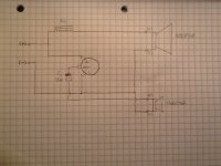
You were correct in your assessment of my diagram! These eyes must be getting old as I absolutely missed the uninsulated wire in parallel with the inductor after the positive input terminal. I have drawn and included a revised diagram. The IN, OUT and C indicated on the L-pad are what is printed on the back of the L-pad at those positions.
I see you ended up aquiring those other speakers. Have you given them a good listen yet? How do they sound?
Attachments
Last edited:
The circuit diagrams in post #17 and 23 are identical, and they also match the actual layout in a set of W60 speakers that i have on the bench for repairs (bad or missing solder joints on the terminal strip). You can see poor soldering in his picture (post #8) where they soldered to the rivets instead of the terminal solder loops.
The L-PAD (passive attenuation device) is actually two separate power pot windings or rheostats with separate wipers on the same shaft. The IN winding comes in at the top of 50R, and the C winding at the bottom of 400R. The separate wipers are soldered together with a piece of hookup wire and labelled as OUT.
The L-PAD (passive attenuation device) is actually two separate power pot windings or rheostats with separate wipers on the same shaft. The IN winding comes in at the top of 50R, and the C winding at the bottom of 400R. The separate wipers are soldered together with a piece of hookup wire and labelled as OUT.
For some reason i couldn't edit my post, so i want to save my measurements here.
The circuit diagrams in post #17 and 23 are identical, and they also match the actual layout in a set of W60 speakers that i have on the bench for repairs (bad or missing solder joints on the terminal strip). You can also see an example of the poor soldering in Ggizzy's picture (post #8) where they soldered to the rivets instead of the terminal solder loops.
The L-PAD (passive attenuation device) is actually two separate power pot windings or rheostats with separate wipers on the same shaft. The IN winding comes in at the top of 50R, and the C winding at the bottom of 400R. The separate wipers are soldered together with a piece of hookup wire and labelled as OUT.
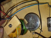
The coil is wound with solid wire 18 AWG with a green plastic jacket. The inductance and ESR were measured at 120 Hz as 11884 uH and 521 mR; at 1kHz as 933 and 1253; at 10kHz as 821 uH and 6.2 R.
The capacitor is marked Dubilier Capacitor Metallized Paper, 12.0 uF +/- 20%, 150VDC WKC, and it does measure 12 uF on the LCR meter.
The circuit diagrams in post #17 and 23 are identical, and they also match the actual layout in a set of W60 speakers that i have on the bench for repairs (bad or missing solder joints on the terminal strip). You can also see an example of the poor soldering in Ggizzy's picture (post #8) where they soldered to the rivets instead of the terminal solder loops.
The L-PAD (passive attenuation device) is actually two separate power pot windings or rheostats with separate wipers on the same shaft. The IN winding comes in at the top of 50R, and the C winding at the bottom of 400R. The separate wipers are soldered together with a piece of hookup wire and labelled as OUT.
The coil is wound with solid wire 18 AWG with a green plastic jacket. The inductance and ESR were measured at 120 Hz as 11884 uH and 521 mR; at 1kHz as 933 and 1253; at 10kHz as 821 uH and 6.2 R.
The capacitor is marked Dubilier Capacitor Metallized Paper, 12.0 uF +/- 20%, 150VDC WKC, and it does measure 12 uF on the LCR meter.
For the 10" bass speaker with the red magnet i measured the following:
120 hz 1313 uH 6.71R
1 kHz 1051 uH 8.44R
10kHz 587 uH 24.5R
Sorry i wanted to put this all in one post, but the editing feature prevented this...
120 hz 1313 uH 6.71R
1 kHz 1051 uH 8.44R
10kHz 587 uH 24.5R
Sorry i wanted to put this all in one post, but the editing feature prevented this...
Chris,
i got your PM and sent a reply back, let me know if you need any help with the circuit.
Maybe if i make enough posts i will be able to reach the edit level...?
i got your PM and sent a reply back, let me know if you need any help with the circuit.
Maybe if i make enough posts i will be able to reach the edit level...?
Interior pictures
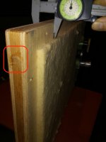
Here's a picture of the very heavy back cover showing the thickness and ports thru which it was filled with sand.
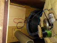
Also the interior (with wiring too short to lay open for access),
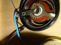
The coil, pad and cap,
and the interior of the L-PAD.
Here's a picture of the very heavy back cover showing the thickness and ports thru which it was filled with sand.
Also the interior (with wiring too short to lay open for access),
The coil, pad and cap,
and the interior of the L-PAD.
Attachments
Last edited:
The one thing I always apply with loudspeakers is that we must move with the times. Don't wish to be considered a Philosopher, but really life is lived in the in the present moment! 😀
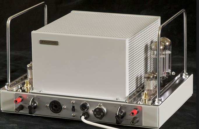
I grew up listening to some goodish valve amplification. In the 1960's the Radford STA-25, IIRC. Considered collectable these days.
Back in the day, we used analogue vinyl LP sources of music, Garrard 401 turntables and Decca London Cartridges.
TBH, speakers were basic!
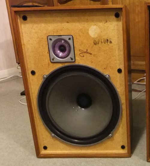
Not much different from these 12" bass plus 3" cone tweeter Wharfedale Melton II, though Goodmans made similar stuff:
I do assure you, that if you had a big well carpeted room and some superior LP music like Frank Sinatra with Count Basie, you could get quite swept away! 🙂
What's the joke? Nostalgia ain't what it used to be....
These days, we design on Microsoft Windows with stuff like Visaton Boxsim.
It pretty much works like the computer predicts it. And we apply much higher order filters to keep distortion down, because computers are very good at aligning phase and level. And there is a definite mathematical theory behind it. Steen Duelund figured this all out about 20 years ago. It's right.
IMO, after too many years doing this, it doesn't get much better than Troels Gravesen's SEAS 3-way classic:
SEAS-3-Way-Classic
The past is dead and gone. Everything there at Troel's website is available. Now.
I grew up listening to some goodish valve amplification. In the 1960's the Radford STA-25, IIRC. Considered collectable these days.
Back in the day, we used analogue vinyl LP sources of music, Garrard 401 turntables and Decca London Cartridges.
TBH, speakers were basic!
Not much different from these 12" bass plus 3" cone tweeter Wharfedale Melton II, though Goodmans made similar stuff:
I do assure you, that if you had a big well carpeted room and some superior LP music like Frank Sinatra with Count Basie, you could get quite swept away! 🙂
What's the joke? Nostalgia ain't what it used to be....
These days, we design on Microsoft Windows with stuff like Visaton Boxsim.
It pretty much works like the computer predicts it. And we apply much higher order filters to keep distortion down, because computers are very good at aligning phase and level. And there is a definite mathematical theory behind it. Steen Duelund figured this all out about 20 years ago. It's right.
IMO, after too many years doing this, it doesn't get much better than Troels Gravesen's SEAS 3-way classic:
SEAS-3-Way-Classic
The past is dead and gone. Everything there at Troel's website is available. Now.
Last edited:
Thank you!
Howdy Steve,
Wow, thanks a bunch, i love the looks of that tube amp and that's a really great website link.
i'll have to look into boxsim; i didn't simulate it but i have made some measurements at both ends of the knob.
Howdy Steve,
Wow, thanks a bunch, i love the looks of that tube amp and that's a really great website link.
i'll have to look into boxsim; i didn't simulate it but i have made some measurements at both ends of the knob.
Attachments
The thing I take from these ancient woofers is that they were highly efficient and very lively and detailed. The definitely had some thing good about them...
Most folks think it was low mechanical loss, i.e. a high Qms:
The high efficiency bass is a bit of a problem with modern tweeters. They struggle to be loud enough. The Eminence Alpha-8A for instance, which is quite retro in some ways, comes in near 92dB. The Beta-8A is nearer 95dB.
ALPHA-8A - Loudspeakers | Eminence Speaker
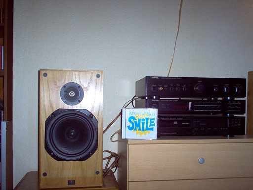
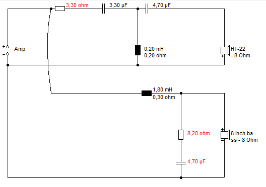
These days, you look for horn loaded tweeters to match that, except for a couple of modern domes like the Audax TWO34 or one SB Acoustics dome that gets near 95dB. I used a less efficient old 90dB 8" Elac bass here ( modern equivalent is SEAS CA22RNX, IMO ) with a similarly retro Monacor HT-22 90dB cone tweeter:
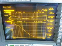
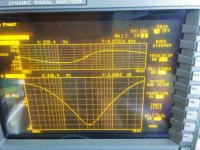
More modern Crossover, of course, with lower distortion:
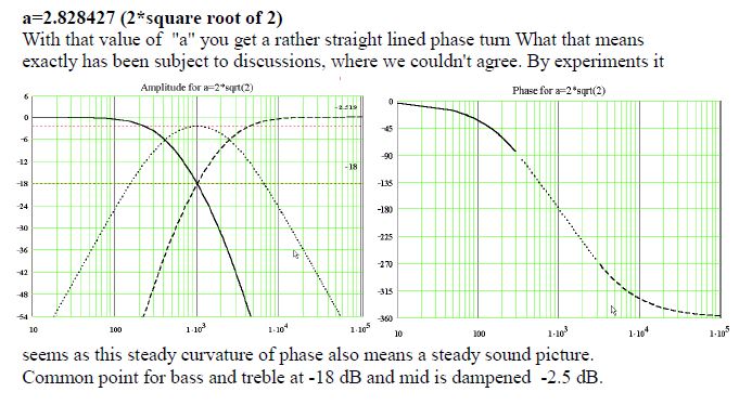
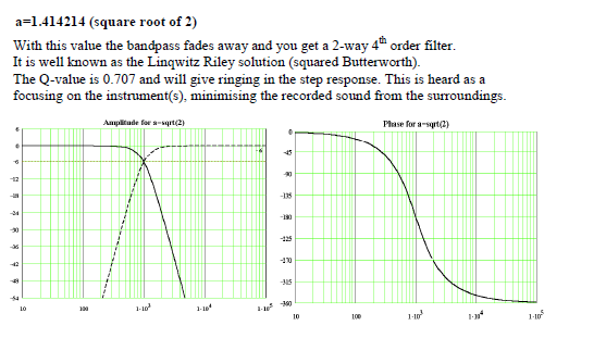
And the LR4 maths which drives the design, though the above is actually around 3kHz crossover:
A very good 2 way, IMO. A lot to like for a relaxing sound. You take the beating from the narrow dispersion, but good and much more mellow than dome tweeters, IMO. And very retro inspired.
Most folks think it was low mechanical loss, i.e. a high Qms:
SpeakerBuilding.com - Interview with Joachim Gerhard of Audio Physic, Page 1Joachim Gerhard said:Q - Many "old" paper woofers still sound astonishingly good compared to modern drivers?
A - Oh, yes. We have not always went to the better. What many driver manufacturers have done the last years, is to increase the damping to make the frequency response more flat. But some old drivers, like the famous 6,5" paper woofer that Jan Paus at Seas made several years ago, (The Seas CA 17 RCY, ed. note) was optimized for low loss. So they made a compromise between frequency response and sensitivity. This driver was very good, and was used by Wilson Audio for many years.
Later, in the 80's, manufacturers started to add more mass, they added more damping, and they made surrounds with high loss. That gave an extremely flat frequency response, but also a lot of energy storage. This compared, the old drivers were much quicker. They had some resonances, but you could get rid of that in the crossover. It was this run for flat response that gave a lot of modern drivers this dull, uninteresting sound. And you can also measure higher second and third harmonic distortion in some of them. If you compare the on-axis response between an old and new driver; you will see that the energy in the treble is far higher than in the new drivers.
These so-called "modern" drivers often has a Qms of maybe 0.8 or 0.6. The old drivers had Qms values of maybe 5 to 7! We found that drivers with a very high mechanical Q sound more open, more clean and dynamic. And when you look at it, you find it is very simple, because they have less loss. The surround is easier to move, the spider is better constructed, they have better air flow, higher sensitivity. So a high mechanical Q is a very good indicator of energy storage behavior. This is one of our secrets. One of the many!
The high efficiency bass is a bit of a problem with modern tweeters. They struggle to be loud enough. The Eminence Alpha-8A for instance, which is quite retro in some ways, comes in near 92dB. The Beta-8A is nearer 95dB.
ALPHA-8A - Loudspeakers | Eminence Speaker
These days, you look for horn loaded tweeters to match that, except for a couple of modern domes like the Audax TWO34 or one SB Acoustics dome that gets near 95dB. I used a less efficient old 90dB 8" Elac bass here ( modern equivalent is SEAS CA22RNX, IMO ) with a similarly retro Monacor HT-22 90dB cone tweeter:
More modern Crossover, of course, with lower distortion:
And the LR4 maths which drives the design, though the above is actually around 3kHz crossover:
A very good 2 way, IMO. A lot to like for a relaxing sound. You take the beating from the narrow dispersion, but good and much more mellow than dome tweeters, IMO. And very retro inspired.
Last edited:
One of my W60 echoes too much sometimes so I looked at the inside if it is an L-pad issue. The capacitor is new one and I suspect L-pad because it still has the original L-pad. The case tells that it is 50ohm but a pair of resistance in it are not same. One is 50ohm and the other is 500ohm. I don't know whether this is designed in this way.
I opened up the L-pad and two coiled wires are different in length and material. I guess they are supposed to be different. Is there anyone who actually measured the L-pad in W60?
I opened up the L-pad and two coiled wires are different in length and material. I guess they are supposed to be different. Is there anyone who actually measured the L-pad in W60?
- Home
- Loudspeakers
- Multi-Way
- Wharfedale W60 crossovers