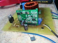
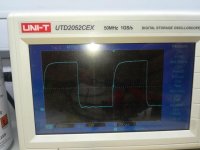
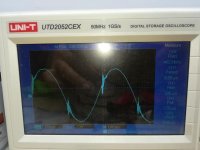
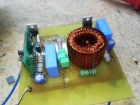
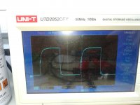
friends hello i applied this schematic to the sine signal at the output is problematic what could be the reason your ideas are important, thank you.
Attachments
-
 38481150_551404058637772_6071125483385257984_n.jpg77.3 KB · Views: 231
 -
 38491878_1886015468370198_2396641534133927936_n.jpg58.6 KB · Views: 193
 -
 38500073_1695053183926494_5124578020639637504_n.jpg69.8 KB · Views: 186
 -
 38600176_2165166906889234_8724638471643201536_n.jpg69.7 KB · Views: 196
 -
 38633628_286239442109652_2175253252973527040_n.jpg65 KB · Views: 192
Hmm, I can't realize what about the Wharfedale Titan yet?
problem signal corrupted
Attachments
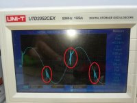
Could be a bit of shoot through.
And yes not a thight PCB design .....
Schematics?
Looks like 25 ohm gate resistors ... sounds like way too much ... probably causing the very slow switching to positive .... try to change to less than 10 ohm
Do the fets get any hot?
What is the psu voltage?
What are det drivers?
And yes not a thight PCB design .....
Schematics?
Looks like 25 ohm gate resistors ... sounds like way too much ... probably causing the very slow switching to positive .... try to change to less than 10 ohm
Do the fets get any hot?
What is the psu voltage?
What are det drivers?
Could be a bit of shoot through.
And yes not a thight PCB design .....
Schematics?
Looks like 25 ohm gate resistors ... sounds like way too much ... probably causing the very slow switching to positive .... try to change to less than 10 ohm
Do the fets get any hot?
What is the psu voltage?
What are det drivers?
Gate resistor 15R, supply 2x48v, no heating, hexfet irfb422,pcb will do a better PCB , just to try the PWM module
- Status
- Not open for further replies.