Hi
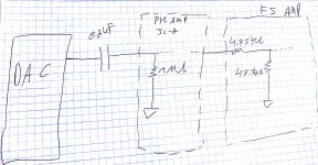
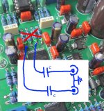
After moving from computer digital source to CDP I notice that I don’t have volume control.
I read about it reading in the forum, nut its hard for me decide where to put the potentiometers and what the best value. (pic attached)
The all stage are DIY projects from this forum") , so I think is better to use mono potentiometers instead of stereo?(different gain for each channel)
, so I think is better to use mono potentiometers instead of stereo?(different gain for each channel)
Thanks everybody
After moving from computer digital source to CDP I notice that I don’t have volume control.
I read about it reading in the forum, nut its hard for me decide where to put the potentiometers and what the best value. (pic attached)
The all stage are DIY projects from this forum
, so I think is better to use mono potentiometers instead of stereo?(different gain for each channel)Thanks everybody
Attachments
Hi,
In this case with a DAC source and a presumed impossibility*
of overdriving the preamp the volume should go between
the preamp and power amplifier.
rgds, sreten.
* Redesign the preamp if it can overload, too much pointless gain.
Redesign the power amplifier it it also has too much pointless gain.
In this case with a DAC source and a presumed impossibility*
of overdriving the preamp the volume should go between
the preamp and power amplifier.
rgds, sreten.
* Redesign the preamp if it can overload, too much pointless gain.
Redesign the power amplifier it it also has too much pointless gain.
thanksits usually sources - selector switch - attenuator - preamp - power amp
whats the value of this attenuator? (bast for SQ)
and what about the attenuator for each channal, its ok?
thanks
in case that you need balance function , go for two mono decks
some info worth reading :
http://www.diyaudio.com/forums/diyaudio-com-articles/186018-what-gain-structure.html
http://www.firstwatt.com/pdf/art_b1_man.pdf
some info worth reading :
http://www.diyaudio.com/forums/diyaudio-com-articles/186018-what-gain-structure.html
http://www.firstwatt.com/pdf/art_b1_man.pdf
Problems…
Problems…
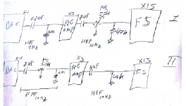
If I put 20k potentiometer after the 0.2uf I get 100 Hz HPF !!!
Maybe I need to put the potentiometer after the pre?
After the pre I have 2uf cap, so if I put the potentiometer there I get 10Hz HPF, but then the F5 "see" ~20k instead 47k !
What to do?
thanks
Problems…
If I put 20k potentiometer after the 0.2uf I get 100 Hz HPF !!!
Maybe I need to put the potentiometer after the pre?
After the pre I have 2uf cap, so if I put the potentiometer there I get 10Hz HPF, but then the F5 "see" ~20k instead 47k !
What to do?
thanks
Last edited:
F5 needs to see as low you can make it
so , no problems there
problem is in overal setup - why you need that cap after DAC and why it needs to be so small and is there need for buffer on DAC output ..........
we can't help , knowing just one sketch
you need to write more about DAC and overall setup ; pics can help , too
so , no problems there
problem is in overal setup - why you need that cap after DAC and why it needs to be so small and is there need for buffer on DAC output ..........
we can't help , knowing just one sketch
you need to write more about DAC and overall setup ; pics can help , too
Ok
I bay the famous kit with AK4396 DAC with differential output that goes to opamp, some guys here sys that the opamp (HPF, buffer) ruin the sound and 0.2uf cap is enough to coupling the DC, after check I hear that is true! So I connect cap after the DAC.
About the pre: I have the jc-2 preamp pcb (in the pic) after the dac->cap, so HFP 0.2uf+1M is ok.
The problem is that I put there potentiometer 20k I get 100hz HPF! I don’t know if the DAC can feed 5uf cap (than the HPF is 1Hz).
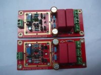
123.jpg: my pcb is the output amp nodule and feedback caps. Without the phono amp.
I bay the famous kit with AK4396 DAC with differential output that goes to opamp, some guys here sys that the opamp (HPF, buffer) ruin the sound and 0.2uf cap is enough to coupling the DC, after check I hear that is true! So I connect cap after the DAC.
About the pre: I have the jc-2 preamp pcb (in the pic) after the dac->cap, so HFP 0.2uf+1M is ok.
The problem is that I put there potentiometer 20k I get 100hz HPF! I don’t know if the DAC can feed 5uf cap (than the HPF is 1Hz).
123.jpg: my pcb is the output amp nodule and feedback caps. Without the phono amp.
Attachments
Last edited:

Put the vol pot as late in the "system" as you can.
Just before the Power Amplifier is usually the best arrangement to minimise unwanted noise.
Any Sources that cannot drive the cable together with the input impedance of the next Receiver in the line need a Buffer. That is the Source needs the Buffer. You do not add a Buffer at the input of a Receiver.
If a coupling cap rolls off the wanted audio signal, then increase the cap value, or parallel in a larger cap. This is the suggestion of Rane (or Whitlock?) for coupling balanced impedance line which are often (unnecessarily) of quite low Receiver Impedance.
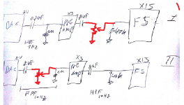
fix picture
You might get away with the setup shown in pic I since the AK4396 delivers only 1.2V_peak per phase and likely won't drive the preamp into clipping, but it will sound inferior to pic II setup because every gain stage performs better when driven with lower level signal and because no SS amp likes the pot directly at its input.
Anyway, it's easy to rewire from pic I to pic II and hear the difference...
hi
after test the DC coupling vs op-amp in the output of the DAC:
hear: high frequency no difference, low frequency: with the cap, i think the DAC hard to drive the pick bass.
spectrum: more 10db noise floor with cap.
i think i move to:
DAC->opamp->potentiometer 20k->F5
thanks
after test the DC coupling vs op-amp in the output of the DAC:
hear: high frequency no difference, low frequency: with the cap, i think the DAC hard to drive the pick bass.
spectrum: more 10db noise floor with cap.
i think i move to:
DAC->opamp->potentiometer 20k->F5
thanks
That is the normal set up for locating the vol pot.
Two things you need to check:
1.) can the DAC output overload the opamp input?
2.) can the vol pot drive the cable and the Receiver equipment (F5)?
vol pot as late in the "system"
Two things you need to check:
1.) can the DAC output overload the opamp input?
2.) can the vol pot drive the cable and the Receiver equipment (F5)?
- Status
- This old topic is closed. If you want to reopen this topic, contact a moderator using the "Report Post" button.
- Home
- Amplifiers
- Pass Labs
- whare to place the volume potentiometers in my system and what the value?