Hi,
I am brand new to this forum. Please let me know if I'm violating any rules. I'm in the middle of my WHAMMY build and I am stalled due to missing/incorrect parts. I sent an email of to the diyaudiostore customer support.
In the meantime it seemed like the opportune time to ask a few questions about the build. I am building the stock version of the kit. Mine came with the AMVECO 12.5 VA + 12.5 VA/18 V + 18V transformer. I am using the red LEDs in the power supply section for reference voltage.
1) My op amp is labeled 458,000 JRC A133 A. I can't find the data sheet for it. Should I be using the optional 22uF/25V caps at C26 and C27 or should I jumper those pads? My understanding is that if this op amp is bipolar, I should use the caps.
2) In the build guide the shielded cable used for inputs/outputs has the shield connected at both ends....at the jacks and at the pcb. In all the preamps I have built I was advised to connect the shield at the jacks, but not at the pcb. Doing so, I was told, could induce ground loop hum. What should I be doing here?
3) I've read all the threads about wiring the panel mounted LED, but I'm still confused. A clear 5mm LED was supplied with my kit. Given the transformer I have at what specific pads on the pcb should the anode and cathode be attached? What value resistor should I attach in series with the anode? If after attaching the resistor I wish to lessen the brightness of the LED I could increase the size of the resistor, correct?
Thanks in advance,
John
Attachments
See the parts list for the kit. It should be a NJM4580. Verify though the store. I found a data sheet for it, but it did not specify case markings. That specific opamp, is a bipolar. My personal guess is that there's a very high probability that the opamp included is bipolar.Hi,
1) My op amp is labeled 458,000 JRC A133 A. I can't find the data sheet for it. Should I be using the optional 22uF/25V caps at C26 and C27 or should I jumper those pads? My understanding is that if this op amp is bipolar, I should use the caps.
Funny - I tried to do a search for that case marking, and this thread has already come up.
The general rule is that for the kit, if the part is included, stuff it. 😀
https://www.mouser.com/datasheet/2/294/NJM4580_E-1917560.pdf
Which build guide are you using? What pictures or step numbers? In 6L6's guide, he's using a 2 + shield cable and wiring it for R, L, and GND. That is the correct way to wire it with that type of cable. Without the signal ground connected at both ends, you won't have music.2) In the build guide the shielded cable used for inputs/outputs has the shield connected at both ends....at the jacks and at the pcb. In all the preamps I have built I was advised to connect the shield at the jacks, but not at the pcb. Doing so, I was told, could induce ground loop hum. What should I be doing here?
https://guides.diyaudio.com/Guide/WHAMMY+headphone+amplifier/3?lang=en
Steps 23, 24, and 26 illustrate what I'm mentioning. However, note the different wires used in 25. This (I assume) is due to changes in the kits over time and various wire types included along with the change to the HP jack.
Either way, if you have 3 conductors, you need L, R, and GND connected at all points. The cable's "shield" in steps 23, 24, and 26 is being used to wire the signal ground.
Not sure what resistor was included in your kit. Did it come with a parts list / stuffing values? Usually it will be noted as Rled or something similar.3) I've read all the threads about wiring the panel mounted LED, but I'm still confused. A clear 5mm LED was supplied with my kit. Given the transformer I have at what specific pads on the pcb should the anode and cathode be attached? What value resistor should I attach in series with the anode?
I think this person has a nice summation.
https://www.diyaudio.com/community/...dphone-amp-guide.317803/page-222#post-6973869
Yes, you can increase the resistance (They say size doesn't matter) 🙂If after attaching the resistor I wish to lessen the brightness of the LED I could increase the size of the resistor, correct?

Thank you for your replies ItsAllInMyHead. I saw that data sheet, but I couldn't reconcile the part number. Who would I ask at the diyaudiostore? I thought all tech questions went to the forum.See the parts list for the kit. It should be a NJM4580. Verify though the store. I found a data sheet for it, but it did not specify case markings. That specific opamp, is a bipolar. My personal guess is that there's a very high probability that the opamp included is bipolar.
Funny - I tried to do a search for that case marking, and this thread has already come up.
The general rule is that for the kit, if the part is included, stuff it. 😀
https://www.mouser.com/datasheet/2/294/NJM4580_E-1917560.pdf
Which build guide are you using? What pictures or step numbers? In 6L6's guide, he's using a 2 + shield cable and wiring it for R, L, and GND. That is the correct way to wire it with that type of cable. Without the signal ground connected at both ends, you won't have music.
https://guides.diyaudio.com/Guide/WHAMMY+headphone+amplifier/3?lang=en
Steps 23, 24, and 26 illustrate what I'm mentioning. However, note the different wires used in 25. This (I assume) is due to changes in the kits over time and various wire types included along with the change to the HP jack.
Either way, if you have 3 conductors, you need L, R, and GND connected at all points. The cable's "shield" in steps 23, 24, and 26 is being used to wire the signal ground.
Not sure what resistor was included in your kit. Did it come with a parts list / stuffing values? Usually it will be noted as Rled or something similar.
I think this person has a nice summation.
https://www.diyaudio.com/community/...dphone-amp-guide.317803/page-222#post-6973869
Yes, you can increase the resistance (They say size doesn't matter) 🙂
I used 6L6's build guide. My understanding is you need two wires to transmit a signal. If you don't use shielded cable, you twist the wires to reduce noise. The shield is designed to do the same thing. For example, I built Roy Mottram's VTA SP14 preamp. The shield is only connected at the RCA jack buss....not at the pcb. But I am going to follow your suggestion which is what is in the guide. At worst it'll hum and I can undo the shield at one end.
The explanation for the LED is much appreciated. The resistors were all thrown into an unmarked plastic bag. I have 4 resistors left over because I used the red LED voltage reference in the power supply. The only other resistor I have is a 100 ohm resistor which should have been 10k ohms. That's one of several missing parts. There was no parts list. The values are only printed on the pcb and the schematic. By the way, I bought the full kit.
The chassis is really nice...then again it was $100.
Thanks again for your help,
John
Hi John -
Not sure how I missed you post notification. Sorry for the late reply. Hope all's going well with your build. Total drag that you may have gotten some incorrect parts. I'm sure you've triple checked, but be sure that you didn't stuff the 10k somewhere that the 100R was supposed to be.
I do love that chassis. It's a bargain for what you get. It wasn't available when I built several WHAMMYs. So, I learned to gouge metal with hand tools more effectively with each build. 😀
I know where you're going re: the shield wire. I'd have to see that precise amp and schematic and whether or not the chassis was being used for signal current return or some other mechanism. I'm certainly not saying it's wrong. For this amp, and in this configuration, if you'd like to know how your build would likely operate if you don't connect the input signal GND, then this gentleman may have some insights. That's one of the reasons I love this place. We've all had some issues, and we share them openly.
https://www.diyaudio.com/community/threads/seeking-help-for-whammy-amp.385037/#post-6992771
Cheers,
Patrick
Hi Patrick,
Thanks for checking in. There really aren't that many resistors on the WHAMMY board. I've measured them all and I am truly missing a 10K resistor. The diyaudiostore made everything right so I can proceed.
The chassis is beautiful. Based on the fact that others have had hum issues due to the volume pot not being grounded through the case and the fact that the main ground is a machine screw inserted through the chassis, I am thinking you need to remove the anodized finish wherever the top, bottom, front, rear, and side plates meet. You also need to remove the finish where the volume pot and the ground screw meet the chassis. This is easy enough with a Dremel tool.
With regard to the shielded cable it's easy to connect the shield at both ends. If there is hum, lift one end.
Thanks again,
John
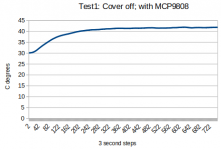
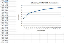
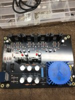
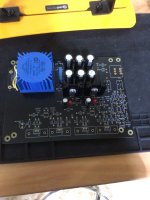
I built the Whammy and it was fun but now I am temperature logging some of my gear which stings my fingers. PNG Wham9808 shows the setup of the I2C temperature sensor.
My Whammy has the Amveco xfmr with 2x18vac. The 78/79-15 with green LEDs outputs 17.1vdc. There is 60ma bias that needs more than 120ma from the regulators. There is 9v dropped across the regulators so they run hot.
With the cover off, the temp. is reasonable at 40C. With the covers on, it is more than 49C. This is not terrible but it's too much for my liking.
I have the large black case that comes with the Whammy complete kit. I see some kits are stuffed in an unvented Hammond case and they have more voltage with 2x22vac that the regulators must dissipate.
The Amveco 70053 on the schematic is obsolete but there are substitutes at Digikey for $32CAN + $20 shipping. I also tested the 21vdc regulator option. But wait .. the max voltage of the JRC4580 is 18vdc. The OPA2604 is 15vdc. I think there is some design oversight here. What can be done?