Hey all.
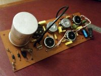
Anybody tell me where on the schematic is this resistor? What are it's values..Schematic can be found here http://www.vintagehofner.co.uk/britamps/watkins/schematics/westminmk9.html

Thanks in advance! 👍
Anybody tell me where on the schematic is this resistor? What are it's values..Schematic can be found here http://www.vintagehofner.co.uk/britamps/watkins/schematics/westminmk9.html
Thanks in advance! 👍
Isn't it the 1.5k 1W between the two halves of the can-cap? (Shown widely separated on the schematic.)
That was my first thought thanks, think thats correct..Isn't it the 1.5k 1W between the two halves of the can-cap? (Shown widely separated on the schematic.)
Is this know as the internode point? Just wondering why someone replaced it with such a large sized resistor, schem says 290v on that rail...If I replace do I need a certain resistor, what type would you recommend?
Plan is replacing plate/grid stoppers/grid leak, all the caps except the can, add new tubes and hopefully bias.Yeah, and check the capacitor also. It could be bad, causing the resistor to fail.
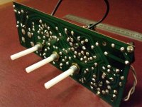
Heres a few pics of the board beforehand..
Bit novice but hoping to learn as I go, do a good job, really want to keep this little amp, good 10w home practice thing to play on.


Actually the large can capacitor is the one most likely to be degraded, or bad, of all the parts.
It has the highest voltage, temperature, and ripple current.
Of the other capacitors, only the blue electrolytic is worth replacing. The rest will be ok.
The resistors should be ok, just measure them and see. Clean all the pots and sockets, though.
When you replace the burnt resistor, keep it standing off the board so there is 1/4" of space under it.
Last edited:
Man alive don't say that!Actually the large can capacitor is the one most likely to be degraded, or bad.
It has the highest voltage, temperature, and ripple current.
Can't find any replacement, I don't think they make one of similar dimensions...50+50+50uf, red 50uf outer plain neg...Dated 1974
With all the tube guitar amplifiers being used today, there are many new replacements available.
Make sure you get the right voltage rating.
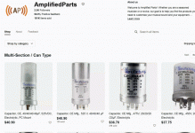
https://www.ebay.com/str/amplifiedparts/Multi-Section-Can-Type/_i.html?store_cat=29062453017
Make sure you get the right voltage rating.
https://www.ebay.com/str/amplifiedparts/Multi-Section-Can-Type/_i.html?store_cat=29062453017
The link is the ebay store of Amplified Parts.
https://www.amplifiedparts.com/
You could also contact Hayseed Hamfest. They will custom make a can cap with the values you need.
https://hayseedhamfest.com/pages/quote
https://www.amplifiedparts.com/
You could also contact Hayseed Hamfest. They will custom make a can cap with the values you need.
https://hayseedhamfest.com/pages/quote
Amplified Parts is a large guitar amp parts and related items dealer. They've been around a long time,Your link goes to an ebay store that doesn't sell anything, what you getting at?
and stock a large selection of the newly made Mallory multi-section electrolytic capacitors,
which is now called CE Manufacturing. Of course you can buy them elsewhere as well, that is just an example.
Some of the guitar amp techs aren't very enamored of the CE caps. They generally prefer F&T caps, even if they have to replace them with 2 or more individual caps to make up what the can had in it.
S.
S.
If that can cap is soldered to the board, it is worth investing in a solder sucker so it is easier to remove. I had to remove some phillips capacitors that have 3 connections, and it is quite easy to unwittingly put some upward pressure on a delicate copper track, and lift it off the board.
You don't need to replace it with a can - 3 seperate 50uF caps will work fine and they are quite a lot smaller these days.
You don't need to replace it with a can - 3 seperate 50uF caps will work fine and they are quite a lot smaller these days.
On the older WEM Dominators that resistors was across a free standing cap, it forms part of a RC lowpass filter and drops the HT to the following stages. You can see it got hot,burned the PCB and has probably failed in the past. It should be mounted about 1/2" or so off the board.
To check if the cap has failed use your meter on AC volts to check the ripple, anything over 100mV and it's suspect. It'd be better to replace it and do a thorough job whilst you have the PCB out.
Andy.
To check if the cap has failed use your meter on AC volts to check the ripple, anything over 100mV and it's suspect. It'd be better to replace it and do a thorough job whilst you have the PCB out.
Andy.
Is this suitable replacement- https://www.tubesandmore.com/products/capacitor-ce-mfg-350v-50505050-f
Does mine have three 50uf or four?
50 + 50 + 50 then it says "red 50uf outer" not sure what outer means..
Yeah it may come down to that looking at costs...I may even strip out the old caps from inside can, good learning curve for me.You don't need to replace it with a can - 3 seperate 50uF caps will work fine and they are quite a lot smaller these days.
Plan replacing couplings/elecrolytics/filter caps - Then send power through to run a diagnosis from point to point, may not need to replace can cap but getting feeling I will as it's dated over 50 years old...To check if the cap has failed use your meter on AC volts to check the ripple, anything over 100mV and it's suspect. It'd be better to replace it and do a thorough job whilst you have the PCB out.
Andy.
Thanks everyone for advice, got parts on order..
- Home
- Amplifiers
- Tubes / Valves
- WEM Westminster MK9 SCHEMATIC question
