Had someone message me on ebay this morning about a transistor matcher/curve tracer I sold them.
Apparently it stopped working.
So they decided to have a scope about.
He says I have applied 24 volts to a 3.3 v reg that has max input of 16 volts.
He says that I have made a stupid mistake.
My reply is that you can apply 24 volt rail to a 3v3 reg if 3v3 reg ground is at 12 volts.
I took a 24 volt supply and split it into +/-12 volts using a class b transistor pair with a 12v zener on transistor bases.
Is it possible that on either power up or power down that a transient disturbance of the two voltages could harm the 3.3Vreg? Either that, or the sequencing of the voltage rise of the two Vregs is not right? Example: the 24V hits it operating voltage before the 12V one does upon power up.
I have sold about half a dozen with no problems.
He got back to me this evening and says it is working again.
Thinks it might be a bad USB connection.
The lower centre rail volts is set via a zener through a transistor so cant go above 12 volts.

He got back to me this evening and says it is working again.
Thinks it might be a bad USB connection.
The lower centre rail volts is set via a zener through a transistor so cant go above 12 volts.
Looking at your eye soring schematics you should be more careful calling your customers idiots. There is a good chance of overvoltage spikes due to possible imbalance of the 47uF caps - and this is NOT clamped by the zener at the common base.
Out of curiosity, what regulates the upper (RAW+12v) with respect to the GND?
I ran a quick sim impulse from 24v to 36v in, and the RAW-12v is clamped WRT GND by the zener, but the upper rail seems to follow the input voltage.

I'm probably missing something obvious..
I ran a quick sim impulse from 24v to 36v in, and the RAW-12v is clamped WRT GND by the zener, but the upper rail seems to follow the input voltage.
I'm probably missing something obvious..
Attachments
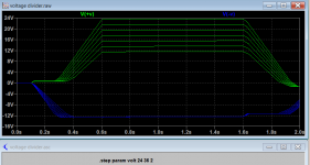
The input voltage is a regulated 24 volts from a wall wart.
The zener and transistors ensure the middle voltage is always around 12 volts.
The circuit works as I have sold numerous pcb's with that power supply circuit.
The circuit is similar to an amplifier class B output stage.
I get its unusual but it works.
It doesnt matter if one rail comes up first the -ve volts is just a op amp supply.
Its the top voltage which is important as it has a microcontroller on it as well as op amps.
Looking at your eye soring schematics you should be more careful calling your customers idiots. There is a good chance of overvoltage spikes due to possible imbalance of the 47uF caps - and this is NOT clamped by the zener at the common base.
Of course its clamped. The zener and bottom transistor have a diode and zener like circuit.
As for eye watering schematics, what a load of old bollocks !
Sold 3,000 copies and most people loved it.
You have completely misunderstood my "idiot" comment.
I was referring to the customer thinking "I" was an idiot not me thinking he was one.
The circuit is highly unusual and can easily catch someone out who doesnt have the schematics.
Last edited:
As for eye watering schematics, what a load of old bollocks !
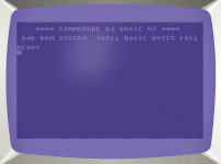
I think that bucks bunny was referring to the choice of colours on a black background which does not make for comfortable viewing.
I suffer from migraines so it has to be a black background.
What colours do you think it should be ?
Its all just small software changes.
Also bear in mind its a low res bmp screen dump.
I had a look at the colours.
Black background so bright colours needed for foreground colours.
I have cyan, yellow, light green and white.
They dont come much brighter than those.
Starting to sound like a "wind up" comment to me.
Last edited:
I can appreciate white on black as it used to be. A background probably shouldn't be stark white. Perhaps some paper colour that isn't fatiguing?
If I'm not mistaken we share a knowledge of a certain computer that uses blue... or is that lavender and lilac, a bit like some forum I know?
If I'm not mistaken we share a knowledge of a certain computer that uses blue... or is that lavender and lilac, a bit like some forum I know?
Attachments
In the 1980's I wrote teletext software for the Commodore 64.
Good old 6502.
The Commodore was a refreshing change after the Sinclair Spectrum rubber keys !
Good old 6502.
The Commodore was a refreshing change after the Sinclair Spectrum rubber keys !
Obviously it is too late to teach you some basics. And you are not willing to learn. But hey, that is not my problemOf course its clamped. The zener and bottom transistor have a diode and zener like circuit.
As for eye watering schematics, what a load of old bollocks !
Sold 3,000 copies and most people loved it.
You have completely misunderstood my "idiot" comment.
I was referring to the customer thinking "I" was an idiot not me thinking he was one.
The circuit is highly unusual and can easily catch someone out who doesnt have the schematics.
Just to set the record straight here is my original ltspice circuit and simulation.
Tests and simulates absolutely fine.
Which I knew anyway as I have sold loads.

Tests and simulates absolutely fine.
Which I knew anyway as I have sold loads.

Whenever I say "what an idiot I am!" I take myself seriously... 😉
And with good reason, most of the times.
And with good reason, most of the times.
lcsaszar,
Gyuri,
Loved your back-to-back comments. I recognise myself in them!
I'm a designer too, but in a different field entirely; a sense of humility is always ...productive 🙂
Gyuri,
Loved your back-to-back comments. I recognise myself in them!
I'm a designer too, but in a different field entirely; a sense of humility is always ...productive 🙂
In the 1980's I wrote teletext software for the Commodore 64.
Good old 6502.
The Commodore was a refreshing change after the Sinclair Spectrum rubber keys !
I used to know the editor of the PET magazine.
If I remember correctly it was published in Cheshire.
I once wrote the circuit for a simple dual switch based on the tone generator.
On the back of a beermat in our local pub.
Andy
Nigel, perhaps you are being a bit defensive as there may be a problem with your circuit because the top part is not regulated. You unwisely depend on a wall-wart SMPS never offering an unregulated voltage spike upon power up. When such a spike occurs it will only appear on your top supply and the overvoltage would kill the 3v3 reg as your Customer observed.

- Home
- Member Areas
- The Lounge
- Well what an idiot !