Hi all,
New to the forum. I discovered this place while searching for answers to a problem I am having with a toroidal transformer. I am building a 9090 that needs a 15-0-15 centre tapped transformer.
I am using this transformer. http://www.digikey.com/product-detail/e ... -ND/299867
And I am having trouble getting the proper voltages out from the secondaries. Per the datasheet:
ttp://media.digikey.com/pdf/Data%20Shee ... ormers.pdf
"For 115V operation, connect the primaries in parallel by connecting yellow and red lead wires together and black and violet leads wires together."
"To connect the secondaries in series, the red and brown wires are connected together. Take the output across the green and blue wires."
Here is a drawing of how I have everything connected. When I measure the voltage, I connect the GND on the multimeter to the red/brown wires and I test the voltage at the blue and green wires. I am not getting 15VA. Does anyone see what I am doing wrong? I am very perplexed by this issue. I have also tried putting a 1k resistor across the blue + red/brown wires and the voltage outputs don't change.
http://imgur.com/55kGYg7
Last edited:
Hi. Yes I am still have trouble. I edited the original post with more information. I accidentally posted earlier and couldn't figure out how to get back to the post to edit it.
Hi all,
New to the forum. I discovered this place while searching for answers to a problem I am having with a toroidal transformer. I am building a 9090 that needs a 15-0-15 centre tapped transformer.
I am using this transformer. http://www.digikey.com/product-detail/e ... -ND/299867
And I am having trouble getting the proper voltages out from the secondaries. Per the datasheet:
ttp://media.digikey.com/pdf/Data%20Shee ... ormers.pdf
"For 115V operation, connect the primaries in parallel by connecting yellow and red lead wires together and black and violet leads wires together."
"To connect the secondaries in series, the red and brown wires are connected together. Take the output across the green and blue wires."
Here is a drawing of how I have everything connected. When I measure the voltage, I connect the GND on the multimeter to the red/brown wires and I test the voltage at the blue and green wires. I am not getting 15VA. Does anyone see what I am doing wrong? I am very perplexed by this issue. I have also tried putting a 1k resistor across the blue + red/brown wires and the voltage outputs don't change.
Imgur
Your wiring and measurement method seem OK, but you write "VA" which is not a unit for voltage. At what setting of the DMM did you measure the voltages?
Two practical things come to mind,
1/ Is your meter set to an AC volts range (and not DC).
2/ Transformer leads are usually heavily lacquered and so getting a good connection can be difficult. I often use a small grindstone on a pcb drill to clean the ends up. Make sure all the leads are down to bright copper.
1/ Is your meter set to an AC volts range (and not DC).
2/ Transformer leads are usually heavily lacquered and so getting a good connection can be difficult. I often use a small grindstone on a pcb drill to clean the ends up. Make sure all the leads are down to bright copper.
Build and use a Mains Bulb Tester.
It will prevent you blowing up your new projects.
It is especially useful when powering ON an unknown mains transformer.
It will prevent you blowing up your new projects.
It is especially useful when powering ON an unknown mains transformer.
It might be helpful if we knew what you are getting. "Not 15VA" does not tell us very much.
Follow Andrew's advice: make and use a lamp limiter. Those of us with experience always do this when first powering up mains-connected items.
Follow Andrew's advice: make and use a lamp limiter. Those of us with experience always do this when first powering up mains-connected items.
Your wiring and measurement method seem OK, but you write "VA" which is not a unit for voltage. At what setting of the DMM did you measure the voltages?
Ah. I thought VA was meant to indicate we were talking about AC voltage.
Two practical things come to mind,
1/ Is your meter set to an AC volts range (and not DC).
2/ Transformer leads are usually heavily lacquered and so getting a good connection can be difficult. I often use a small grindstone on a pcb drill to clean the ends up. Make sure all the leads are down to bright copper.
Yes. My meter was set to AC. I did use a dremmel to clean off the ends and now I am getting 19V on both outputs. Thank you so much for the tip. I don't know how I would have ever figured that out without the internet.
I am thinking that I am getting 19V because our mains is 120V instead of the 115V that the transformer is designed for. I'm weary of plugging it in to the power supply on to the PCB so I will have a look around and see if anyone has used something similar or if I should get a transformer designed for 120V. Consider this problem solved. Thank you!
That's good that you can measure it OK now.
Right... VA is simply volts * amps and is a way of expressing the rating of a transformer. A 3 amp capable, 60 volt winding would be 180va.
The reason the voltage is higher than 15 volts is because of a couple of factors...
1/ Mains voltage certainly can influence things, but its proportional. If the input voltage is 10% high then the secondaries are 10% high too.
2/ The regulation factor of the transformer. The rating of a transformer is specified at max loading and so at light loading the voltages rise by a percentage called the 'regulation' figure. That should be given for the transformer in the specs. Small transformers have much worse regulation than big ones with lots of iron in the core. Figures can range from as much as 60% (yes 60) for a tiny 1.5va transformer to perhaps just 3 or 4% for a large 600va one.
So you need to ask yourself if the 19 volts is to high for the project you intend... it may well be fine.
15 volts AC will give around 21 volts DC when rectified and smoothed, and 19 volts will be nearer 27 volts DC.
What is a 9090 that you mention
Ah. I thought VA was meant to indicate we were talking about AC voltage.
No, VA is the unit used for apparent power.
When talking about voltages, usually only the unit V is used, but then it should be clear from the context whether this voltage is DC or AC.
In this case the conext was the measurement with a DMM directly on the output of a transformer, so immediately I assumed AC.
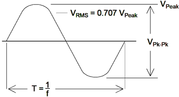
In the case of DC that's all, but in the case of AC there are different ways of expressing the value, Vpeak, Vpeak-peak or Vrms. An image can explain this shorter than I can in words:

If an AC voltage is given without suffix then that normally implies an RMS voltage. This is also what a DMM will show on the display. However, if you were to view it on an oscilloscope, you would see a signal that would look like the image above and you would have to calculate the RMS value yourself.
In this case the measurement was taken with a DMM, which meant the values were in Vrms.
Last edited:
No, VA is the unit used for apparent power.
When talking about voltages, usually only the unit V is used, but then it should be clear from the context whether this voltage is DC or AC.
In this case the conext was the measurement with a DMM directly on the output of a transformer, so immediately I assumed AC.
In the case of DC that's all, but in the case of AC there are different ways of expressing the value, Vpeak, Vpeak-peak or Vrms. An image can explain this shorter than I can in words:
If an AC voltage is given without suffix then that normally implies an RMS voltage. This is also what a DMM will show on the display. However, if you were to view it on an oscilloscope, you would see a signal that would look like the image above and you would have to calculate the RMS value yourself.
In this case the measurement was taken with a DMM, which meant the values were in Vrms.
AH! Thank you! I'm a new EE student so this is the kind of stuff I like to learn about. I'm glad I kind of learned this now so I won't be making this mistake again. Thank you!
That's good that you can measure it OK now.
Right... VA is simply volts * amps and is a way of expressing the rating of a transformer. A 3 amp capable, 60 volt winding would be 180va.
The reason the voltage is higher than 15 volts is because of a couple of factors...
1/ Mains voltage certainly can influence things, but its proportional. If the input voltage is 10% high then the secondaries are 10% high too.
2/ The regulation factor of the transformer. The rating of a transformer is specified at max loading and so at light loading the voltages rise by a percentage called the 'regulation' figure. That should be given for the transformer in the specs. Small transformers have much worse regulation than big ones with lots of iron in the core. Figures can range from as much as 60% (yes 60) for a tiny 1.5va transformer to perhaps just 3 or 4% for a large 600va one.
So you need to ask yourself if the 19 volts is to high for the project you intend... it may well be fine.
15 volts AC will give around 21 volts DC when rectified and smoothed, and 19 volts will be nearer 27 volts DC.
What is a 9090 that you mention
Yeah I checked and 19V should be fine. I plugged it in to the power supply and I was getting the proper voltages on the power supply output and nothing blew up so I am confident it is okay to move forward.
The 9090 is a DIY clone of the Roland 909. The 9090 project :: the complete TR-909 clone
 Good stuff !
- Status
- Not open for further replies.
- Home
- Amplifiers
- Power Supplies
- Weird voltages on toroidal transformer output