i had mod 3 totally same car amplifier for friends. All of them are working normal with those inverter circuit provide +-25v rail voltages. Now my final mod item for myself which generates +-40v. Those capacitors max voltage are 35v. I really fightened coz my main caps are using mundorf 40v those are too expensive for gambling.
Should I replace the inverter coil to decrease voltage?
Should I replace the inverter coil to decrease voltage?
Attachments
Why worry about *electrical* specifications?
That´s for boring Nerds.
Yours is an AUDIOPHILE !!!!!! amp, only significant parameter is MOJO!!!!! and you have tons of it:
* TUBE PREAMP!!! (in an SMPS powered Car amp).
* MUNDORF caps!!!!!
* ELNA SILMIC caps!!!!!
**** SILVER GOLD OIL MICA caps!!!!!!!!!!!!!!!!!!!!!!!!!!!!! (probably as vitally important for sound Zobels or bypass)
All I can suggest is a Plexiglass cover so everybody can ADMIRE it.
What am I saying? Cover it with a Bohemian Glass plate and nothing lesser.
Oh: DO NOT TURN IT ON ... EVER.
That amp was modded to impress fellow Audiophiles, actual sound enjoying is irrelevant.
40v across a 35v cap is no good.
40v across a 40v spec cap is fine provided other specs are not exceeded such as temperature and ripple currents. Make sure any ripple voltage does not exceed the 40v limit and make sure the 40v really is an absolute limit for the rail under all conditions.
40v across a 40v spec cap is fine provided other specs are not exceeded such as temperature and ripple currents. Make sure any ripple voltage does not exceed the 40v limit and make sure the 40v really is an absolute limit for the rail under all conditions.
You need to test the circuit and out why the voltage is so high.
Maybe a faulty feedback circuit in power supply ?
Maybe a faulty feedback circuit in power supply ?
If you mean manufactured audio designs it-- saves money-saves size of build in this modern micronisation world - but yes a valve/tube has a heater which--yes heats up and does no good long term to any electrolytic millimeters away.
OTOH- cuts down the chances of HF oscillation with very short runs on a PCB to the related active device.
OTOH- cuts down the chances of HF oscillation with very short runs on a PCB to the related active device.
A tube amp in a car?
You must have smooth roads, and good ventilation.
Pointless too, as the power section is solid state, no advantage is gained by using tubes in the front end.
And the high voltages in tubes, you need an AC inverter, another job to do properly.
The best would be to reduce the supply to about 25 volts, how that affects the tube is also to be seen.
Sorry for my earlier post, I got carried away by my distrust about certain kind of components which in my view retard, instead of advancing the Audio development.
Focusing on the specific question, feel we are missing some critical data, others have pointed similar doubts.
WHY????
I see YihCon capacitors there, can´t read voltage and capacitance.
Picture mentions 40V Mundorf caps, you mention 40V supplies, but your OP talks about 35V caps??????
We don´t have enough data; can guess different things:
* proper voltage is +/- 25V and your friends use that. Yes-No
* for some unknown reason you have +/-40V Yes-No
* you actually modded it to have 40V rails?
* is it "broken"?
Picture text claims same.
Do you have a schematic?
What is the amp brand and model?
A you see, way more questions than possible answers.
Focusing on the specific question, feel we are missing some critical data, others have pointed similar doubts.
All of them are working normal with those inverter circuit provide +-25v rail voltages. Now my final mod item for myself which generates +-40v
WHY????
I see YihCon capacitors there, can´t read voltage and capacitance.
Picture mentions 40V Mundorf caps, you mention 40V supplies, but your OP talks about 35V caps??????
We don´t have enough data; can guess different things:
* proper voltage is +/- 25V and your friends use that. Yes-No
* for some unknown reason you have +/-40V Yes-No
* you actually modded it to have 40V rails?
* is it "broken"?
Didn´t you say they are 40V?Those capacitors max voltage are 35v
Picture text claims same.
In principle those inverters produce regulated voltge out, changing coils is not the way to adjust them, but altering the control circuit.Should I replace the inverter coil to decrease voltage?
Do you have a schematic?
What is the amp brand and model?
A you see, way more questions than possible answers.
> A tube amp in a car?
My brother has a car with all tube audio. 1941 Plymouth.
I grew up in a 1957 Plymouth and that had to be tubes. Also a 1960 Rambler which would be all tube, but the first time it gave trouble Dad hung a transistor pocket radio on the knob. (He only listened to traffic reports.)
My brother has a car with all tube audio. 1941 Plymouth.
I grew up in a 1957 Plymouth and that had to be tubes. Also a 1960 Rambler which would be all tube, but the first time it gave trouble Dad hung a transistor pocket radio on the knob. (He only listened to traffic reports.)
i have removed the coil and now ordering a tailormade one for replacement. im quite sure the manufacturer did wrong thing....
For the tube, it is working as buffer and tested can improve sound very much. The original one is china 6n11. i replaced it with a Telefunken CCa.
my last production is used all rifa124,126 cap to mod and nothing wrong in 2 years. since my friend wants my amplifier so much it is given him and im now building a new one with cap upgrade to all better spec mundorf and audio note. staging cap between tube and soild im planning to use better silver gold oil 0.33 and one of mkp 2.2-4.7uf. between input opamp and tube i planned to use mundorf silver gold oil 0.22uf but not yet confirm because those are hugh expensive.
ps. added a clc filter and bypass cap wimamkp10 0.1, 0.01, elna 10uf gold leg.
i will keep reporting status if guys are interested in.
Thanks.
Attachments

Last edited:
i have ordered a tailormade coil for replacement.
for my last production, all caps are rifa124,126 which has no any issue in 2 years. as my friend wants it very much, it has been given him and now im building a much better spec for myself. mundorf for powering and audio note and roe for decoupling. silver gold oil for staging. bought 2 Telefunken cca.....
i will update status for you guys if you are interested in.
thanks guys....
i m also want to know which power transistor i can replace for better performance. they are c2837 and a1186. what difference if replaing with sankan or onsemi and which modal can replace them directly?
there are tons of questions need to reply....
i have few of this amplifier so i can cross check with this werid one. i cannot find any information of it from the net. i think it is a china copy one. but anyway checked with the board and actual sound quality which is the best comparing with around 10 soild only amp from the moto repare center.
the normal one, ic tl494 generates a 27khz for 3 uprail and downrail mosfets to the coil. the coil scale should be 5:9 which generates around +-25 when the engine started. another coil 5:11 generates around +-35v for the tube. for the opamps, 7815 and 7915 from 25 to 15. as separating power module only i found the output is +40,-40 +35,-35 so that i can pretty sure the coil must be wrong. with 40v can improve sound much as i know, but it is really not good for those 40v caps and 78,79xx module. i think the coil can upgrade to max 33v max. but considering heat dissipation and power consumption i think i should leave it to be default.
Sorry for my earlier post, I got carried away by my distrust about certain kind of components which in my view retard, instead of advancing the Audio development.
Focusing on the specific question, feel we are missing some critical data, others have pointed similar doubts.
WHY????
I see YihCon capacitors there, can´t read voltage and capacitance.
Picture mentions 40V Mundorf caps, you mention 40V supplies, but your OP talks about 35V caps??????
We don´t have enough data; can guess different things:
* proper voltage is +/- 25V and your friends use that. Yes-No
* for some unknown reason you have +/-40V Yes-No
* you actually modded it to have 40V rails?
* is it "broken"?
Didn´t you say they are 40V?
Picture text claims same.
In principle those inverters produce regulated voltge out, changing coils is not the way to adjust them, but altering the control circuit.
Do you have a schematic?
What is the amp brand and model?
A you see, way more questions than possible answers.
My point was why a tube pre amp feeding a solid state power stage in today's time.
In the old days, nothing else was available, so tubes were used, but as soon as transistors became common, tubes went out of use, except for a few people who still value their sound quality, which came from an all tube stage unit...
Making that is an effort, nice, but in my opinion not very useful...but to each his own...
OK.
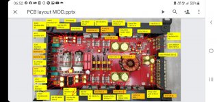
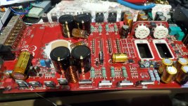
I looked all over the place on the first picture for the SMPS controller IC, couldn´t find (or recognize) it but of course it had to be *somewhere*.
Guess I found it in the second picture, in the small parts cluster, bottom left between the 4700x35 Nichicon and the bottom left Mundorf.
I see you removed the inverter transformer and looked at the (all Chinese 😱 ) spec sheet.
At least we share numbers and some labels 🙂 so I can guess they offer different turns ratios, based on nominal (and that´s the key word: NOMINAL, meaning it can actually vary A LOT in normal use) 13.8V
And different turns ratios give different "raw" voltages.
Problem is, NO amplifier uses such raw unregulated voltage for power.
It woud be crazy to do so, available car voltage may (and does) vary from about 11.5 V (a deeply discharged battery) up to 14.4V , with engine revving up (say on a highway) and battery already charged to the brim, because raw secondary voltage would vary by the same proportion, we are talking 25%.
So nominal 25V rails could actually vary between 26V and 20.8V
So SMPS designers use a controller IC (here TL494 which is a classic) which first boosts battery voltage *beyond* what you need, so even with the weakest battery you still get more than needed, and then regulate it down.
From your datasheet, transformer #4 (5:9 ratio) would give you raw 25V ; BUT those 25V rails will be subject to all the wild variations I mention above, so designer will choose one which gives at least 25V rails with 11.5V car voltage, it would be transformer #6 (5:11 ratio) which on "normal" 13.8V would give you 30V rails and under certain conditions up to 31.3V
But designers typically aim higher, to guarantee output voltage is always regulated, personally I would choose the next higher transformer: #7 (5:12) , nominal 33.1V rails, which*might* sometimes reach 35V rails.
If you measured 40V rails, then he probably chose #9 (5:12 , nominal 38.6V rails).
I see you want to tame that too high voltage by using a lower turns ratio transformer, but that´s not the correct path.
Clearly you have a problem in the Voltage REGULATION circuit, so supply output= raw unregulated voltage, and solution is not a lower voltage transformer but repairing the actual regulation problem.
If not comfortable troubleshooting SMPS circuits, get a regular Tech who repairs Car Amplifiers, that is an everyday problem for them.
Go to the core problem, do not apply band-aids which to boot won´t work well (or at all).
Pity you spent so much money on expensive components and then throw that effort overboard by feeding that amp from a *terrible* damaged supply.
In case it´s not clear: I very much doubt manufacturer fit "wrong" transformer, and highly suspect the voltage regulation circuitry.
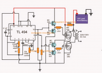
EDIT: the circuit you show is a crude unregulated "12V battery to 220VAC inverter" to power, say, an electric shaver while camping, a proper "amplifier use" supply is like this:

If image does not open: http://www.high-voltage-lab.com/projects/49/bigs/smps.gif
Notice:
1) transformer ratio is "higher than needed", 5:10 so nominal voltage will be 13.8V * 2= 27.6V (real world around 26 or 26.5V because of losses) and yet desired rail voltage is +/-20V !!!!!
2) BUT TL494 has a voltage sensing (and regulating) pin, notice they sample +20V rail through R8 and RV1 and feed it back to TL494 pin 1 son it down regulates "excessive" raw voltage to actually needed one.
Your amp certainly must have same or very similar circuit, which is now malfunctioning.
Replacing transformer is NOT the solution.
Just curious: you sure you didn´t mess with the voltage regulation potentiometer? 😱
You certainly worked on that board, big time.
Curious 2: what power is that amp supposed to deliver?
+/-25V rails are not much, by any means, even if bridged.
Care to share brand and model?
I looked all over the place on the first picture for the SMPS controller IC, couldn´t find (or recognize) it but of course it had to be *somewhere*.
Guess I found it in the second picture, in the small parts cluster, bottom left between the 4700x35 Nichicon and the bottom left Mundorf.
I see you removed the inverter transformer and looked at the (all Chinese 😱 ) spec sheet.
At least we share numbers and some labels 🙂 so I can guess they offer different turns ratios, based on nominal (and that´s the key word: NOMINAL, meaning it can actually vary A LOT in normal use) 13.8V
And different turns ratios give different "raw" voltages.
Problem is, NO amplifier uses such raw unregulated voltage for power.
It woud be crazy to do so, available car voltage may (and does) vary from about 11.5 V (a deeply discharged battery) up to 14.4V , with engine revving up (say on a highway) and battery already charged to the brim, because raw secondary voltage would vary by the same proportion, we are talking 25%.
So nominal 25V rails could actually vary between 26V and 20.8V
So SMPS designers use a controller IC (here TL494 which is a classic) which first boosts battery voltage *beyond* what you need, so even with the weakest battery you still get more than needed, and then regulate it down.
From your datasheet, transformer #4 (5:9 ratio) would give you raw 25V ; BUT those 25V rails will be subject to all the wild variations I mention above, so designer will choose one which gives at least 25V rails with 11.5V car voltage, it would be transformer #6 (5:11 ratio) which on "normal" 13.8V would give you 30V rails and under certain conditions up to 31.3V
But designers typically aim higher, to guarantee output voltage is always regulated, personally I would choose the next higher transformer: #7 (5:12) , nominal 33.1V rails, which*might* sometimes reach 35V rails.
If you measured 40V rails, then he probably chose #9 (5:12 , nominal 38.6V rails).
I see you want to tame that too high voltage by using a lower turns ratio transformer, but that´s not the correct path.
Clearly you have a problem in the Voltage REGULATION circuit, so supply output= raw unregulated voltage, and solution is not a lower voltage transformer but repairing the actual regulation problem.
If not comfortable troubleshooting SMPS circuits, get a regular Tech who repairs Car Amplifiers, that is an everyday problem for them.
Go to the core problem, do not apply band-aids which to boot won´t work well (or at all).
Pity you spent so much money on expensive components and then throw that effort overboard by feeding that amp from a *terrible* damaged supply.
In case it´s not clear: I very much doubt manufacturer fit "wrong" transformer, and highly suspect the voltage regulation circuitry.
EDIT: the circuit you show is a crude unregulated "12V battery to 220VAC inverter" to power, say, an electric shaver while camping, a proper "amplifier use" supply is like this:
If image does not open: http://www.high-voltage-lab.com/projects/49/bigs/smps.gif
Notice:
1) transformer ratio is "higher than needed", 5:10 so nominal voltage will be 13.8V * 2= 27.6V (real world around 26 or 26.5V because of losses) and yet desired rail voltage is +/-20V !!!!!
2) BUT TL494 has a voltage sensing (and regulating) pin, notice they sample +20V rail through R8 and RV1 and feed it back to TL494 pin 1 son it down regulates "excessive" raw voltage to actually needed one.
Your amp certainly must have same or very similar circuit, which is now malfunctioning.
Replacing transformer is NOT the solution.
Just curious: you sure you didn´t mess with the voltage regulation potentiometer? 😱
You certainly worked on that board, big time.
Curious 2: what power is that amp supposed to deliver?
+/-25V rails are not much, by any means, even if bridged.
Care to share brand and model?
Last edited:
first of all the 25v4700 is for the 1st regulation of battery power. i think that is good enoght to replace 3 cheap 3x 16v2200uf.
after the inverter the +-20 to +-26v. depanding input voltage is only for the power transistos for amplifing without further regulation but only diode and my mundorfs.
i understand what you meant, but for the feedback of tl494, it would detect the uprail voltage and if any issue it would stop the circuit but not regulating the voltage but it turns out giving me a perfect +-40v. tl494 should be working as a oscillator, mosfet as a hight current switch and the coil receives the pulse generates related voltage. but could the tl494 regulates voltage from 40 to 25 with the same coil, it is a big question for me.
anyway i have a plan b which is.... mod with another normal board. it only spends me usd300 from the car audio shop.
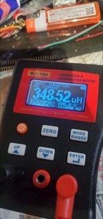
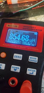
on the other hand, i have a coil/cap meter. when the new coil on hand i can measure the different.
And or i can also remove coil from one of the normal amplifier to test.
anyway my goal is only replace all required components to improve sould quality but not doing in-depth experiment with it. just let see the coil difference before the next step.
thank you so much for those info .
chris
after the inverter the +-20 to +-26v. depanding input voltage is only for the power transistos for amplifing without further regulation but only diode and my mundorfs.
i understand what you meant, but for the feedback of tl494, it would detect the uprail voltage and if any issue it would stop the circuit but not regulating the voltage but it turns out giving me a perfect +-40v. tl494 should be working as a oscillator, mosfet as a hight current switch and the coil receives the pulse generates related voltage. but could the tl494 regulates voltage from 40 to 25 with the same coil, it is a big question for me.
anyway i have a plan b which is.... mod with another normal board. it only spends me usd300 from the car audio shop.
on the other hand, i have a coil/cap meter. when the new coil on hand i can measure the different.
And or i can also remove coil from one of the normal amplifier to test.
anyway my goal is only replace all required components to improve sould quality but not doing in-depth experiment with it. just let see the coil difference before the next step.
thank you so much for those info .
chris
- Home
- Amplifiers
- Power Supplies
- weird voltage