We may see a difference if measuments is properly Gated and from 0, 10, 20, … till 70 degree of axis.I did a small test, put some tape over the slots, as suggested, and captured the FR. No difference.
1 meter, sweep from 100 to 20khz, mic on tweeter level in room.
View attachment 1189956 View attachment 1189957
However the mount of midwoofer is not great.
Also the screws protruding tweeter is not a good solution.
The ridges protrude outwards more than the rest of the baffle. I suppose the effect should be similar to those speakers where the baffle is recessed further back than the sidewalls. Unfortunately I didn't have a thicker tape.If you post the REW file somewhere like Google Drive or Dropbox, we can drill down with the impulse windowing and see if there are tiny differences. But they will be very tiny. Ideally you would want the tape to be as round as possible, not pushed into the gaps.
Also, the tape needs to smooth the step from the baffle to the corner, because this is the first step encountered by the wavefront and will have the most dramatic effect.
Here is the REW file.
Attachments
I did an experiment covering whole frontbaffle with felt making sure everything was perfect smooth. Baffle was already optimized. Maybe the woolfelt i used was not dense enough, but my conclusion is felt is not worth the effort . It is better to have smooth hard surface.The felt actually works, but the kerfed corners are more likely something from the marketing department.
Felt may be used to improve diffraction in some situations. Remember one experiment on WWW where thick felt between tweeter and midwoofer gave some improvement.
Think speaker was with tweeter offset on the baffle (uneven power respons).

Those measurements are weirdly inconsistent. It looks like you have some interference around 1KHz, and also possibly clock drift unless the mic or speaker were changing position a lot or moving during the measurement. This can happen if you are standing near the mic which causes it to move during the measurement.
The impulse responses should all look nearly identical. There is a lot of pre-ringing on some of them which suggests there is DSP somewhere messing with the measurement.
If you look at the group delay plots, it curves differently for each measurement. With this much timing variation it is pretty much impossible to see the moment the wavefront hits the edge of the baffle.
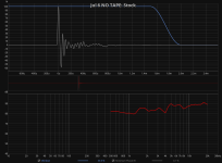
Generating minimum phase resulted in consistent impulse responses.
The main difference is at 340uS or 4.6 inches, which I'm guessing is close to the distance between the tweeter and baffle edge. There is a lot of ringing and the samplerate/BW is low, so it's just a small variation in a larger wiggle.
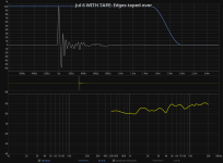
Here is the effect of the tape on the response:

Peaks and dips of the comb filtering in the treble are about 2.7KHz apart which has a wavelength of 370uS which is close enough to the time delay seen on the impulse response.
The main difference is at 340uS or 4.6 inches, which I'm guessing is close to the distance between the tweeter and baffle edge. There is a lot of ringing and the samplerate/BW is low, so it's just a small variation in a larger wiggle.
Here is the effect of the tape on the response:
Peaks and dips of the comb filtering in the treble are about 2.7KHz apart which has a wavelength of 370uS which is close enough to the time delay seen on the impulse response.
Attachments
Last edited:
It does look pretty awesome. I used to own Kappa 8's. Was surprised by the apparent cheapness of the drivers in comparison to the wonderfully made cabinets. They sounded ok
What should I do to improve the measurements?Those measurements are weirdly inconsistent. It looks like you have some interference around 1KHz, and also possibly clock drift unless the mic or speaker were changing position a lot or moving during the measurement. This can happen if you are standing near the mic which causes it to move during the measurement.
The impulse responses should all look nearly identical. There is a lot of pre-ringing on some of them which suggests there is DSP somewhere messing with the measurement.
If you look at the group delay plots, it curves differently for each measurement. With this much timing variation it is pretty much impossible to see the moment the wavefront hits the edge of the baffle.
Should I change my signal path?
The mic didn't move between the measurements. The speaker on the other hand i might have moved slightly while i was putting on the tape. Although I did my best to not disturb it.
The distance between the center of the ribbon tweeter and the edge of the baffle is 10cm or around 4 inch.
To see if it's clock drift, do several measurements in a row without changing anything or getting up from the chair, and see if the group delay charts stay the same.
The worst group delay shift was 914ms, which is about 1 foot. It would be hard not to notice if something moved 1 foot forward during the measurement.
EDIT: To make it more obvious, use a right window of 2ms.
The worst group delay shift was 914ms, which is about 1 foot. It would be hard not to notice if something moved 1 foot forward during the measurement.
EDIT: To make it more obvious, use a right window of 2ms.
Yeah, overall best to have as smooth/slick as practical same as is required for SoS land speed record vehicles.It is better to have smooth hard surface.
- Home
- Loudspeakers
- Multi-Way
- Weird roundover(?) design to combat cabinet edge diffraction