Lately i want to find out if a power pentode can be used as a low (or even normal) noise preamplifier.
I want to be honest so i will say that what i really want to do is use an RF linear power amplifier as a receiver preamplifier in ;order to use it's tuning system for added selectivity.
It doesn't matter if you are in to RF because the same principle should apply to audio frequencies.
If a power pentode has a low noise floor and it is matched to input and output impedance should work as a preamplifier also regardless it's small signal gain.
Thank you in advance
Chris
From your description it sounds like you are at least familiar with the principles involved in a low noise preamp.
Why don't you post a circuit that may have resulted from your thoughts on what might work.
Many here on DIY will comment for sure, 👍
Why don't you post a circuit that may have resulted from your thoughts on what might work.
Many here on DIY will comment for sure, 👍
There are very low noise pentodes and even lower noise triodes, it is unlikely that most transmitter pentodes/beam tetrodes are that quiet. Might be worth looking at what it would take to design a simple preselector / rf amplifier circuit with an appropriate device.
So this will be used at audio? Yes. No, Maybe?? 🙂the same principle should apply to audio frequencies.
Sounds like a recipe for fire'd eggs... I concur with the above post; perhaps one of the circuits here will do;
https://industrial-electronics.com/measurement-testing-com/rf_design_7.html
I'm pretty sure I built the circuit in Fig 2 when it was a Radio-Electronics project article, for SW radio preselection.
https://industrial-electronics.com/measurement-testing-com/rf_design_7.html
I'm pretty sure I built the circuit in Fig 2 when it was a Radio-Electronics project article, for SW radio preselection.
Well i agree with all of you and of course i am not familiar with low noise concepts involving larger tubes and especially beam tetrodes, with low power tubes and especially triodes like ECC88 yes i can calculate the expected noise.
Kevinkr
That is my next step but i want to try reverse connecting the linear amplifier also just for fun, in fact i use cascode ECC84 for many of my low noise projects with RF.
jhstewart9
No it is about rf and not audio and that is why i asked because i can't find any relevant information anywhere.
Wik
It is sure wasted energy but the linear is always on anyway and it consumes the same energy in receiving mode.
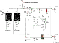
Here is an almost exact circuit (the input tuner will be manual), i feel that i am out of topic but i will post it in order to see what i want to use as a preamplifier just because everything is there and it would be nice to be able to use it in receiving also with the added bonus to be able to approximately tune the amplifier in receive mode and then fine tune in tx mode.
Chris
Kevinkr
That is my next step but i want to try reverse connecting the linear amplifier also just for fun, in fact i use cascode ECC84 for many of my low noise projects with RF.
jhstewart9
No it is about rf and not audio and that is why i asked because i can't find any relevant information anywhere.
Wik
It is sure wasted energy but the linear is always on anyway and it consumes the same energy in receiving mode.
Here is an almost exact circuit (the input tuner will be manual), i feel that i am out of topic but i will post it in order to see what i want to use as a preamplifier just because everything is there and it would be nice to be able to use it in receiving also with the added bonus to be able to approximately tune the amplifier in receive mode and then fine tune in tx mode.
Chris
Attachments
Last edited:
jjasniew
I forgot to add that nowadays i don't like to use anything solid state that is vital for comunications and it is connected to the outside world using an antenna or unfiltered mains.
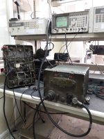
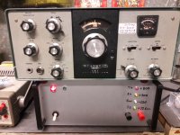
Just for fun here are two of my rigs, i have many other like R390 etc...
I think got enough out of topic so i will stop talking rf, only noise in big rf tetrodes and pentodes.
Chris
I forgot to add that nowadays i don't like to use anything solid state that is vital for comunications and it is connected to the outside world using an antenna or unfiltered mains.
Just for fun here are two of my rigs, i have many other like R390 etc...
I think got enough out of topic so i will stop talking rf, only noise in big rf tetrodes and pentodes.
Chris
Attachments

That circuit is a Class B Linear Amplifier used in Single Sideband Transmitters.No it is about rf and not audio and that is why i asked because i can't find any relevant information anywhere.
Wik
SSB is terrible at audio. But very effective for voice communication systems. Audio is usually 300 - 3500 Hz.
A group of sub channels below 300 Hz are used for which receiver is meant as the target.
There is about a 9 db increase in effective comm ability. 👍
Attachments
Exactly hence my question if someone has tried it before, it is all there in the amplifier and it will be on anyway, why i shouldn't use it a receiver preamplifier also?
I will try it anyway but i though that it might be a good idea to ask here where many people know better about tubes.
Of course some bias adjustments or a different bias circuit could be needed but it is not something difficult to tackle.
Chris
I will try it anyway but i though that it might be a good idea to ask here where many people know better about tubes.
Of course some bias adjustments or a different bias circuit could be needed but it is not something difficult to tackle.
Chris
Last edited:
For this lineup to work at audio you can throw away all of the components with the exception of one EL519, its socket & screws.
Replace the RF Choke (RFC) in the plate cct with a 5-10 H Choke parelleled with 5-10K resister.
Two EL519s do not make less noise, that increases by root of 2 with two toobz.
At the input spigot you will need another choke of 5-10H & a cap of ~330microF.
In a Class B stage the biasing is close to cutoff, OK in a PP stage.
But in SE the result is an entire spectrum of even order distortion products (2H. 4h. 6H, Etc).
Keep us posted on how the build goes. And the 'sweet' sound that spills forth. 😀
No i mean to work as a receiver preapmplifier in RF not audio ie connect the input to the antenna and the output to the receiver.
Probably i didn't wrote the post clear enough as English is not my first language.
Chris
Probably i didn't wrote the post clear enough as English is not my first language.
Chris
from 1,6 to 30 Mhz, basically the HF band.
Basically what i want to try is make the power amplifier a receiver preamplifier on the same frequency that it is tuned ie in transmit it will be used as a power amplifier for SSB and during receive as a receiver preamplifier but i don't know if it will have an acceptable noise figure so i asked here if anyone has tried it in the past.
Basically what i want to try is make the power amplifier a receiver preamplifier on the same frequency that it is tuned ie in transmit it will be used as a power amplifier for SSB and during receive as a receiver preamplifier but i don't know if it will have an acceptable noise figure so i asked here if anyone has tried it in the past.
Up to 30 Mhz there is not much to be gained with a low noise receiver front end,
The background atmospherics & man made noise limit what can be done, Ordinary pentodes like 6AU6 & 6CB6 get us there very quickly.
A tuned stage on the front end is useful, it is effective as a way to improve image rejection, something in every superhet RX.
The same tube used in a combined SSB Linear amp looks incompatible tho. This is an audio forum, probably not much help here.
At 100 MHz commercial FM & 144 MHz, the 2m band cascode using tubes like the 6BQ7 work well.
During the 50s & 60s many people built all band convertors to use for mobile work. These converted to the BC band at ~One to 1,5 MHz.
I gebuilt three, one a 3-30 MHz thing, Another for 50 MHz / 6m & another with junk parts for 7 MHz / 40m.
The All Band Converter has a gross error in construction. Can anyone see it, in plain view? 😱
Attachments
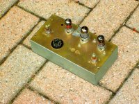
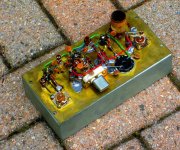

Well i think there is an inductor missing where the variable capacitor is.
Other than that i can see an empty hole where a variable capacitor is missing judging from the bolt pattern.
Other than that i can see an empty hole where a variable capacitor is missing judging from the bolt pattern.
The only other think i can see or rather i can't see are the crystals but you can use lc oscillators also and a black wire connecting the RF input or outpout PL259 connector to a banana terminal which looks like the grounding post.
I can't see if the tube near the variable capacitor is in a socket or just left there.
I can't see if the tube near the variable capacitor is in a socket or just left there.
The all band convertor uses a local oscillator that is continuous tuned about One MHz higher freq than the RF front end.
Adjacent unshielded coils can interact with each other, forming dead spots on the tuning dial. Lesson learned but otherwise it worked OK.
This one has a Pentode RF Amp, a Triode 6C4 separate local Oscillator driving a Pentode mixer & a Pentode broad banded IF amp.
All the pentodes are 6BH6 to conserve heater power, The auto receiver AGC can be connected to automatically control gain.
The knob on the front panel controls RF Gain. Built around 1960, still here on the shelf.
The coils were all tuned using a Boonton Radio Corp (BRC) 260A Q-Meter. BRC soon after became part of Hewlett Packard (HP),
The 3-gang tuning cap is a cut down broadcast band cap. Many people did that, The box is Aluminum, formed in the lab workshop, by me.
I joined HP in 1965, no laptops & no printers. All that changed soon tho. 👍
- Home
- Amplifiers
- Tubes / Valves
- Weird question about noise in power pentode tubes.