Hi everyone!
I'm in the process of replacing the crossover parts of my Cabasse MT 3 Jersey speakers with better ones (hopefully).
The cap replacement way easy, so I bought a LCR meter to measure the coils and now I'm stucked and need your help.
The coil for the tweeter circuit has 2 sets of wire strands and are marked in the pictures bellow as A, B, B1 and C. On the PCB, B and B1 are soldered together and marked as B.
On the continuity test, A-B is the first strand and B1-C is the second one. When measured, A-B shows 0,000 (not null), B1-C is 0,211mH and A-C is 0,580mH (B and B1 connected).
The DCRs are:
A-B - 0.6 ohm
B1-C - 0.7 ohm
B-C - 0.9 ohm (B and B1 connected)
A-C - 1.2 ohm (B and B1 connected)
The wire(s) used for this coil are 0.25mm in diametre.
What values (mH, ohm) shoud I take into considerations when searching for the replacement coil(aircore)?
What's the purpose of a 2 wire strands(3 ends) coil in this crossover?
Thank you very much!
Attachments

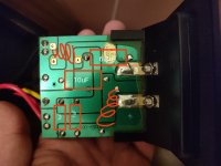
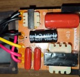
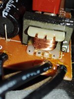
No, the coil was removed from the PCB, as shown in the first picture. The other 2 pictures are from the second crossover which is still untouched, as I wish to do a before/after comparison.
I might have assumed the A-B inductance to be maybe 140uH. However the resistance measuerements don't add up. B ought to equal B1.
Have you nulled your leads? (Short them and subtract this)
Are the two windings the same gauge?
Have you nulled your leads? (Short them and subtract this)
Are the two windings the same gauge?
A-B inductance is zero (0.000) on my LCR meter not Ø, as it tries to measure it but it settles on 0.000. A-B resistance is 0.6 (sometimes 0.5) ohm.
B-B1is null/Ø - cannot be measured because they are 2 diferent wires.
B1-C is 211mH and 0.7(sometimes 0.8) ohm.
B-C (B and B1connected/shorted) is also 211mH but 0.9(sometimes 0.8) ohm.
A-C (without B and B1 connected/shorted) is null (Ø), cannot be measured because they are 2 diferent wires.
A-C (B and B1 connected/shorted) is 0.580mH and 1.2 ohm (sometimes 1.1)
The two windings are the same gauge.
Attachments
You might just want to leave the transformer or tapped choke alone. I am fairly sure the purpose is to match tweeter impedance to the woofers.
We would need more details about the drivers in order to suggest changes.
We would need more details about the drivers in order to suggest changes.
The DC resistance of the tweeter is 6.8 ohm, woofers are 7.8 each (2 drivers). Can't measure the actual impedance of the drivers because I don't have the necessary equipment.
It is probably not worth changing the pair of 1 uF capacitors or the 6.8 uF orange drop capacitors.
The little choke on the woofers looks like a good choice to replace with an air core as long as you match the DC resistance.
Not sure if you will hear a difference by changing the 10 uF electrolytic with a film type.
The little choke on the woofers looks like a good choice to replace with an air core as long as you match the DC resistance.
Not sure if you will hear a difference by changing the 10 uF electrolytic with a film type.
I bet the AC value is beyond the meters range, and therefore settles on 0.
I doubt that coil has anything to do with the tweeter, but info is needed.. I'll look at this harder later.
I doubt that coil has anything to do with the tweeter, but info is needed.. I'll look at this harder later.
All the capacitors are already replaced with ClarityCap ESA(2*1uF, 10uF) and ClarityCap CSA(6.8uF). The only parts that i need to replace are the coils. Can I alter the DC resistance of a coil by adding a resistor in series with it? The coil on the woofers circuit is the only one left to be measured.
The coil on the woofers which is not the tapped one seems to be the most likely to see some improvement for the speakers.
You want an air core coil with low enough DCR to match the existing coil. It may be hard to measure the RC resistance with a typical ohm meter.
Might want to look for something matching the inductance that has 14 gauge wire or better.
You want an air core coil with low enough DCR to match the existing coil. It may be hard to measure the RC resistance with a typical ohm meter.
Might want to look for something matching the inductance that has 14 gauge wire or better.
The coil for the tweeter circuit is the smaller one on the crossover pictured above.
Dave, thank you for the picture.
Dave, thank you for the picture.
The inductor is part of a third order crossover network. The tappings B and B1 adjust the sensitivity to suit the tweeter . The crossover network for the bass/midrange speakers is a second order network.
Last edited:
Ok, so how do I treat this coil with 3 ends (B and B1 are soldered together on B point on the back of the PCB, so it ends up being A-B-C) if I inted to replace it a "standard" 2 ends coil? Between A and B I get no reading (actualy is 0.000 not null), regardles of B and B1 wire ends soldered together or not, B1(or B soldered to B1) to C is 0.211 mH and A to C is 0.580mH.
Do I measure on point A and C to find out its inductance, or B to C and then A to C and sum their values?
Managed to measure the coil on the woofer circuit, it's 0.770mH and 0.3 ohm, and it only has 2 ends. 🙂
Do I measure on point A and C to find out its inductance, or B to C and then A to C and sum their values?
Managed to measure the coil on the woofer circuit, it's 0.770mH and 0.3 ohm, and it only has 2 ends. 🙂
The inductance reading measured from A and C, with B and B1 joined together, is the reading that matters (0.580mH). If you convert your crossover to use an air cored inductor you will need to consider adding an "L" pad to the tweeter circuit.
Why would it be necessary to use an L pad if I can (hopefully) match the specs of the original coil (mH and ohm)? The iron core inductor behaves differently from an air core inductor?
Apologies in advance for the dumb questions.
Apologies in advance for the dumb questions.
It is better to ask questions to avoid mistakes. The iron core inductor is in reality an auto-transformer. If the tapping point (B and B1) was set at 50% of the coil winding turns, then only approx. half of the signal voltage would be sent to the tweeter. This is a neat method of matching the sensitivity of the speakers.
If you replace the inductor with an air wound type, you will need to link B to A on the PCB.
If you replace the inductor with an air wound type, you will need to link B to A on the PCB.
Things are starting to make sense now. The weird thing is that I get 0.000 mH reading on A to B, but the resistance is 0.6 ohm, and 0.211 mH on B(or B1) to C.
Would it be ok to replace the original coil with 2 coils, one connected to A and B(580mH - 211mH) and the second one connected to B-C(211mH) or would I run into other problems?
Would it be ok to replace the original coil with 2 coils, one connected to A and B(580mH - 211mH) and the second one connected to B-C(211mH) or would I run into other problems?
If VaNarn is correct when saying it is an autotransformer, it would be a different situation. Autotransformers usually require a larger base inductance and not likely air core candidates. It's interesting that we had one similar to this only a week or two ago, I wish I could find it.
Does B-C change when you short A-B?The weird thing is that I get 0.000 mH reading on A to B,
- Home
- Loudspeakers
- Multi-Way
- Weird crossover coil