BTW, this amp was out of an Allen organ. I think someone mentioned Allen earlier. It's pretty clean underneath and at first glance it doesn't look messed with as the soldered connections "look" original. I'll be interested in what others think.
Regards John L.
Regards John L.
Interesting... it looks like none of the heater wires are twisted.
But I don't see any rodent nests or burn marks, so aside from the wax and bumblebee caps (they're leaky by now), nothing too concerning.
But I don't see any rodent nests or burn marks, so aside from the wax and bumblebee caps (they're leaky by now), nothing too concerning.
That schematic is obviously incorrect.  The graphic shows SS rectification and the chassis contains vacuum rectifiers. The graphic shows a small signal pentode and the chassis does not have any small signal pentodes.
While it's a royal PITA, tracing things out slowly and carefully will have to be done.
The graphic shows SS rectification and the chassis contains vacuum rectifiers. The graphic shows a small signal pentode and the chassis does not have any small signal pentodes.While it's a royal PITA, tracing things out slowly and carefully will have to be done.
I agree Eli. First time I've actually taken a look at the schematic. I'm going to have to be a bit patient getting into this. I'll start sketching it out tomorrow.
Thanks for your interest folks.
Regards John L.
Thanks for your interest folks.
Regards John L.
Thanks for your interest folks.
It's easy to get interested in this sort of project. The starting materials of nice "iron", twin 5U4s, and a good mechanical engineering package attract attention.
IMO, an easy mechanical fix is replacement of those old screw type I/P connectors with this sort of RCA jack. Use red for the right channel and black for the left channel. The die cast metal housings will keep chassis strength up.
BTW, Soviet surplus K40 paper in oil (PIO) parts are highly suitable as replacements for the OEM "bumblebee" capacitors. You get those off "EBone". A Jim McShane point is mixing cap. dielectric type up to hear the amp, not the capacitors. So, replace the waxed paper caps. with 716P series "Orange Drops", which are discrete polypropylene film/aluminum foil and copper leads.
Eli, do you think it's a practical thing to re-locate the input sockets to the rear, or is there a danger of picking up unwanted noise from the transformers?
Shielded wiring works, but you'd be close to the AC power cable and that leaves me uncomfortable. Speaking of the AC power cable, a proper, 3 wire, safety grounded cable, with correct "bonding" is in order. In HIFI service, that chassis will not be buried inside cabinetry.
While jacks on the front panel are anything but "the greatest thing since sliced bread", You will have to deal with the openings the OEM connectors occupy. Introducing new holes into the sheet metal weakens things. No matter how you twist and turn, the look will remain "industrial". FWIW, I suggest leaving well enough alone and (where possible) repurpose existing sheet metal openings.
While jacks on the front panel are anything but "the greatest thing since sliced bread", You will have to deal with the openings the OEM connectors occupy. Introducing new holes into the sheet metal weakens things. No matter how you twist and turn, the look will remain "industrial". FWIW, I suggest leaving well enough alone and (where possible) repurpose existing sheet metal openings.
I've decided to remove the existing 2 wire AC input and replace it with a filtered 3 prong socket along with a new fuse holder. The existing AC wires were hardened probably from overheating. I shall also fit your suggested RCA jacks that are recessed. Then I'll try the amp out without any other mods to assess it. After that, let's see where we need to go.
Regards John L.
Regards John L.
When I took the spring shields off the OP valves, they are 12AU7A's and not 12AY7's as noted on the chassis. Is this going to make a difference to be concerned about?As Eli mentioned, the 12AY7 tubes could be worth a pretty penny depending on what they are (and if they test good!). Also, just some interesting trivia: I believe the Neumann U67 used a 12AY7 (much more obtainable than the VF14 in the U47/U48).
John L.
The labeling on the chassis clearly shows 12AY7. Somebody shoved the pin compatible, but electrically different, 'U7 in. The $64 question is whether or not parts changes "under the hood" accompanied the tube type change.  The underneath photo suggests that changes were not made, but it's all guessing, without the OEM schematic.
FWIW, I'd buy 2X 12AY7s from a reliable dealer, like Jim McShane. It's unlikely that the installation of 'U7s will cause outright damage. Rather performance will be degraded. Remember, that in circuits with NFB loops, net gain is controlled by the NFB network. What will unfavorably change is distortion and damping factor.
The underneath photo suggests that changes were not made, but it's all guessing, without the OEM schematic.FWIW, I'd buy 2X 12AY7s from a reliable dealer, like Jim McShane. It's unlikely that the installation of 'U7s will cause outright damage. Rather performance will be degraded. Remember, that in circuits with NFB loops, net gain is controlled by the NFB network. What will unfavorably change is distortion and damping factor.
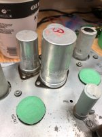
I've been trying to source the three multi section caps shown in the pic that I need for this amp. No luck so far and I've tried the local rep. for Cornell-Dublier who asked the factory but came back empty handed. Also Digi-Key and Mouser. Anybody know where I might get hold of these values? If I can, I'd like to get the correct values.
2 pcs -Two section 10mfd 400v
One pc -Three section 30 mfd - 500 wv, 15 mfd - 450 wv & 100 mfd - 50 wv
Also, down in the lower left is a ceramic Resistor mounted in a clamp -100 ohms that (seems) to be an extension to the horizontal power resistor that is next to it on the chassis top. I've had trouble finding anything that looks like that as well.
Regards John L.
Attachments
The values are not exactly the same, but you may still find something useful from this manufacturer Ask Jan First ® ; electron tubes and more
Thanks for the heads up. And of course I should have noted "the lower right" and not left.The values are not exactly the same, but you may still find something useful from this manufacturer Ask Jan First ® ; electron tubes and more
Regards John L.
- Status
- Not open for further replies.
- Home
- Amplifiers
- Tubes / Valves
- Webster tube amp