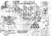
I had posted this query recently on another older thread which appears to have withered on the vine. Hoping here to revive the question....My Webcor Phono is model 333 Musicale. No working phono so I plan to convert it to a homebrew guitar amp, although the voltages are a bit low at 290 B+. Uses 2- 6V6s in output. 2 12Ax7s. Has 3 speakers in series that total 8.2 ohms DC resistance. Output transformer primary has FIVE wires. The Brown Center tap goes to a 220 Ohm 2 watt resistor then to ground. Green and red wires go to the Cathodes of the 6v6s. Yellow and Blue wires go to Plates of the 6V6s.
Transformer code is 239-340, which is a Merit transformer from 1953. Other stamped code , I presume, is the Webcor part #: 67P0368, and must be a Webcor part # as it does not correspond to any of the codes I see in the Merit transformer catalogs that I can find on the web by Googling.
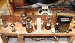
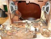
I have attached a few photos of the amp chassis, and a scanned image of the schematic- best I could do as it was brown and crumbly.
So all this is meant to help add more info re the Webcor Musicale, but also chip in with the question of how to wire it. My default will be to leave the output section as is, maybe adding a 25/50 bypass cap, into an 8 ohm load.
I will just rewire the preamp side, maybe using a Silvertone 1482 or Gibson GA16t ( plus or minus the tremolo) schematic for the preamp section.
I have enough homebrew amps and vintage amps, so this is a fun plod- along pursuit. I have so far wired the (2 black) output secondaries to a 1/4" jack, and put in a fuse, illuminated power switch , 3 prong cord, and new filter caps. I may try to bump up the volatge with silicon rectifier to replace the 6X5 or at least put 2 diodes in series with the tube rectifier.
Has anybody encountered an output trannie wired to the cathodes and the plates of the output tubes?
Transformer code is 239-340, which is a Merit transformer from 1953. Other stamped code , I presume, is the Webcor part #: 67P0368, and must be a Webcor part # as it does not correspond to any of the codes I see in the Merit transformer catalogs that I can find on the web by Googling.
I have attached a few photos of the amp chassis, and a scanned image of the schematic- best I could do as it was brown and crumbly.
So all this is meant to help add more info re the Webcor Musicale, but also chip in with the question of how to wire it. My default will be to leave the output section as is, maybe adding a 25/50 bypass cap, into an 8 ohm load.
I will just rewire the preamp side, maybe using a Silvertone 1482 or Gibson GA16t ( plus or minus the tremolo) schematic for the preamp section.
I have enough homebrew amps and vintage amps, so this is a fun plod- along pursuit. I have so far wired the (2 black) output secondaries to a 1/4" jack, and put in a fuse, illuminated power switch , 3 prong cord, and new filter caps. I may try to bump up the volatge with silicon rectifier to replace the 6X5 or at least put 2 diodes in series with the tube rectifier.
Has anybody encountered an output trannie wired to the cathodes and the plates of the output tubes?
Attachments
Cathode feedback wasn't that common in commercial amps - but Fisher, Scott, and Bogen used it on some models... I have some transformers from Wollensak tape recorders that used cathode feedback - the output stage ran from a non-isolated voltage doubler and was isolated by the driver and output transformers.
The 305 V. on the 6V6 plates the schematic shows really can't be argued with, for music reproduction purposes. I'll take a flyer and guess that unit sounded at least 1/2 way decent.
Don't be surprised if the OEM speaker AC impedance was 16 Ω. It must be greater than the measured DCR. So, for guitar purposes, a speaker cabinet with 2X 8 Ω drivers in series could be right.
Wiring "sand" diodes in series with the 6X5 plates will not raise the B+ rail voltage. Buy a 2 A./5 VAC filament trafo and install a 5AR4, which has a smaller forward drop than the OEM 6X5.
Tom and ELI- Thanks for the replies. It does sound decent, both for ceramic phono and for clean guitar tones. I had never encountered a cathode feedback design; not sure if there are any commercial guitar amps with them. I may eventually swap out the Output transformer, but will first see how it sounds with a conventional guitar amp preamp section.
I have 8 ohm and 16 ohm 12 " Alnicos on hand . I will try both out. Jim
I have 8 ohm and 16 ohm 12 " Alnicos on hand . I will try both out. Jim
For a guitar amp if I wanted to raise the B+, I'd pull the 6X5 and put UF4007s in place of it. That would raise your B+ by (1) reducing the drop across the rectifiers, and (2) reducing the load on the transformer.
If it is too clean, couldn't you also remove the cathode feedback connections and tie the cathodes drirectly to the 220 ohm resistor, bypassed or unbypassed. You might want to measure the DC resistance of the cathode feedback winding (cathode to cathode) and add half that much resistance to insure the same operating point.
If it is too clean, couldn't you also remove the cathode feedback connections and tie the cathodes drirectly to the 220 ohm resistor, bypassed or unbypassed. You might want to measure the DC resistance of the cathode feedback winding (cathode to cathode) and add half that much resistance to insure the same operating point.
With cathode feedback it would sound as an ultralinear guitar amp when overdriven. An output stage is as if designed for a guitar amp.
How would this work for the preamp end
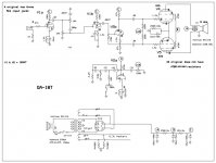
Here is a Gibson 16T/ 18T. I have an original 1959 version. I am now intrigued with just modding the preamp side of this Webcor to GA 18 design (without the tremolo) to hear how it sounds with the Webcor's novel cathode feedback OT.
Any pointers/ needed adaptations as I tie the preamp to pin 5 of the 6V6s?
If it ultimately needs a standard OT such as the Hammond 1620 as specified in this schematic, so be it, but a tighter bassed, cleaner amp for jazz may be the cats meow.
Thanks to all. I am not a newbie but you gentlemen on this forum have forgotten more than I have ever learned.
Attachments
Webcore 333 Musicale rebuild
Thanks to all for the advice. Ultimately I turned this into an experimental chassis. There was room to add an octal preamp tube socket for a 6SN7/6SL7vs 12AY7/12AX7 preamp tube option. I have 3 preamp sockets wired for heaters (two 9 pin, one octal), but will only use 2 sockets max at a time. I replaced the cathode feedback output transformer with a Hammond 125ESE clone to enable push pull and parallel single ended 6v6 variations, I made a solid state 6x5 rectifier to plug into the rectifier tube socket. I currently have it wired as in a variant of the Angela super single ended amp ( to see what a Gibsonette GA-8 may have sounded like) with option for 6sl7 or 12ax7 preamp tubes. As I already had the single ended 6V6 territory covered, I will likely next try a push pull scheme, using 1/2 of a second 12ax7 for a cathodyne PI.
Biggest problem limiting this sonic experiment is the fairly wimpy power transformer- 285 volts B+. Even with SS rectifier and minimal dropping resistors (470 after 1st filter, 1k after 2nd) the 6v6 plates only see 250 V and the preamp tubes only see 85 V. As you might expect, this is a Eddie Van Halen Brown sound dream, with very little clean headroom. I would like to achieve more clean headroom.
As this is a tinkerer's amp project for learning and exploration and not needed for performance, (I have a lotta amps... wife might argue too many) I next plan to reduce the value of the 100k preamp plate resistors (47K or 56K) and/ or reduce the 2.7 V1a and 1.5 K V1B cathode resistors to 1k. I am open to advice. Thanks for the guidance!
- Status
- Not open for further replies.
- Home
- Amplifiers
- Tubes / Valves
- Webcor Musicale OT puzzle