
This is my first post, and I am looking for help in eliminating an unusual and objectionable distortion from an otherwise great-sounding amp. I will attempt to include some scope views and a schematic.
I purchased a Webcor 166-1 amp on EBay. Originally this was built in the 1950s as a phonograph amp, which included a second channel for a microphone. It uses a 6AT6 preamp tube, a 12AX7 phase splitter, and a dual 6V6 power section, with a 5Y3GT rectifier. It has a 10'' speaker. I am hoping for a good-sounding light weight amp and a DIY adventure with a happy ending. My prior projects were restoring some hifi amps (Fisher X202-b and a Magnavox SET home-brew conversion). The guitar amp I have been playing sounds great but is too heavy for me to carry happily (Semour Duncan Convertible 100).
There is some limited information on the web about others who have made this conversion. The 6AT6 input tube invites comparison to a Fender Harvard, and its cathode biased power tubes invite comparison with a Fender Deluxe 5E3, and reportedly DIYers have made some conversions with those classic amps in mind. I recapped the amp, modifying only the 6AT6 input section to match the Harvard 5F10 schematic. It was necessary to modify the input section, as it previously was intended to serve as a microphone input using a circuit that I don't fully understand, and an input jack I have never seen before. I added two input jacks with 68K resistors to the grid of the 6AT6 preamp tube for the high gain channel (formerly the microphone), and the 12AX7 phase splitter for the low gain channel (formerly the phono input). Prior to recapping, the amp passed only the weakest signal, so I replaced all caps with modern equivalents within 10%, at higher voltage limits in most cases.
Recapping was successful, as the amp then sounded really excellent up to the point of slight overdrive, at about 12 o'clock on the volume control. Really special tone up to that point, enough to make it worth continuing. Both channels worked fine, each with their own volume control, and the high gain channel with plenty of volume to really be useable direct from a guitar. Unfortunately, a buzzing sound starts as the volume is increased beyond 12 o'clock. It is a harsh, mechanical sounding buzz, like a loose part. At full volume, the amp certainly is usable and strong but with a fairly raspy distortion that is not musically endearing. The buzzing persists through a known good speaker cabinet, proving that it is an electronic issue, not the speaker or cabinet.
On the oscilloscope (MacCRO, freeware) injecting a 1KHz sine wave, the sine wave is pristine until the volume reaches 12:00. Then, it breaks down immediately by 12:30 with appearance of a negative directed deep spike beginning near the crest of the positive phase, and returning to positive before the negative phase of the sine wave. Please see attached scope views.
This occurs through either the 6AT6 channel or the direct low gain channel (previously the "phono" channel), which just goes directly to the 12AX7 phase splitter. It persists with other known good 12AX7 tubes. It is not altered by switching the 6V6 output tubes.
As an asymmetrical distortion I am suspicious of the very asymmetric phase splitter section in this amp. In that this is not a "clipping" pattern but rather a deep "notch", I do not have a ready explanation for what is happening here, and I am not aware of what would happen in the splitter or elsewhere to cause this. I am posting this because I hope one of you may have experience or ideas which would shed some light.
In the attached schematic, please note the unusual feedback loop from the output transformer to the 6AV6 cathodes, which also seems to serve as a cathode bias arrangement with bypass cap. I may want to play with an alternative cathode bias arrangement without the feedback, as in a Deluxe. Also please note the unusual phase splitter circuit, with the two triodes of the 12AX7 in series (it seems to me). I have not seen this in other guitar amp schematics. Any comments on this would be appreciated. Thanks!


 .
.The phase splitter is basic enough. Your signal feeds into V2, the 12AX7, where it is amplified. That signal in turn is sent to the grid of the upper 6V6.. R11 and R12 are the grid return resistance for that 6V6, but they also form a voltage divider, and the signal at that grid is sampled by that divider, and the result is used to drive the other triode in the phase splitter. The original signal is inverted coming out of the first 12AX7 triode, and so is exactly what the second triode needs to provide opposite polarity signal to the lower 6V6.
You could have a parasitic oscillation going on. Look up that term. Assuming the original amp was stable when it left the factory, I would be suspicious that the construction you did around the inputs may be an issue here. You report either input will create this symptom, but does the 6AT6 stage volume affect the symptom when using the other input? In other words are the two "channels" interactive?
If you can cause the symptom using the low gain direct input, does removing the 6AT6 make a difference?
Did you run any signal carrying wires from point A to point B anywhere? In other words did you add something like a control or jack wiring that adds a few inches of wire? Such wiring can act like an antenna, picking up and radiating signal through the amp. Many home builds have had to correct wiring "dress" problems to make them stable.
Webcor progress report
Enzo suggested that this might be a parasitic oscillation and made some suggestions and proposed some tests. The two channels are not interactive in creating the distortion. Removing the 6AT6 tube does not affect the distortion while using the low gain channel.
I went through the construction I did around the inputs and found several areas for improvement in wiring "dress". The two new inputs, which are open cage type, now have the shortest possible length of cable possible, and now I am using shielded cable with the grounding shield soldered to the ground point shared by other preamp components. The open cage inputs are now insulated from the metal chassis, decreasing the possiblities of a ground loop. I have rerouted mains current and the ground terminal for the three-prong power cord at a distance from the inputs. I also found two connections that seemed to never have been soldered at manufacture (back in the 1950s), and soldered them.
The amp gained some sonic improvement and lost some hum, which is great. The offensive distortion now kicks in with the volume at about 3:00. The amp is therefore more useable at low level play, but still not satisfactory.
I added a defeat switch for the power tube negative feedback loop. This switches off connection from the OT secondary to the 6V6 cathodes, and replaces it with a combined cathode ground for the tubes -- a 200 ohm resistor in parallel with 25uF cap. The original circuit provides cathode grounding with parallel resistor and cap at the center tap of the OT secondary, as a part of the negative feedback circuit.
This defeat switch gave a noticable gain in power and more headroom before the objectionable distortion kicks in. The distortion still prevents using the amp wide open and enjoying it. I installed the switch on the panel and will keep this feature for now.
As suggested by Enzo, I have been reading up on parasitic oscillation (thanks for pointing me in this direction). In addition to careful shielding and dress of the input section, it seems like having proper grid resistors is important. Looking at the schematic for the Fender Deluxe 5E3 as well as the Harvard 5F10 (similar period amps with similar tube complement to my Webcor), it seems that a grid resistor in series with the the coupling capacitor is standard (1500 ohm). The Webcor has 470Kohm resistance between grid and ground, but only a coupling cap between the phase splitter tube plate and the 6AV6 grid. Could this be the source of my parasitic oscillation? The Webcor, of course, was not envisioned as a guitar amplifier, and its circuit might have to be adapted to solve my problem.
So, with the above changes, here are some scope views. I have to believe that the clues are all here, and that someone out there will recognize them. Now, with a 100 Hz sine wave and the volume at 3:00, here is the distortion seen previously:
View attachment 242757
It shows a nice symmetrical soft clipping pattern (sounds so nice) with a wicked sharp brief downward spike just as the waveform passes the isoelectric point. This does not repeat on the downward limb of the wave, only on the upstroke. Its downward deflection is much greater in amplitude than the clipped sine wave itself. What allows that high negative voltage to get through?
Now, switching off the negative feedback to the 6V6s, and changing nothing else, we see that we have gained headroom against the wicked downstroke, which is now much smaller:
View attachment 242758
There are two new spikes appearing however. These are just after the crest and trough of each wave, and are also sharp spikes in the opposite direction of the prevailing voltage change. Possibly the negative feedback is successful at supressing them. I am not clear on what creates such sharp spikes, however.
Finally, at full bore with negative feedback off, here is the waveform:
View attachment 242759
The pattern looks so specific. I wish I had the electronics background to interpret it. Would a parasitic oscillation be so sharp? Could a capacitor be triggered to fire like this with a falling voltage? Would love to hear opinions on this.
Failing a specific diagnosis, I may have to fall back on copying the phase splitter circuit from the schematic of a benchmark amp such as the Deluxe or Harvard. I'm thinking about adding a grid resistor to the 6AV6 as seen in these amps, as a first step.
I am a newbie at all of this amp building. My experience is limited to one kit tube amp that I built. I really have no business giving advice, but here goes . I'll share my experience.
I had a problem that sounds similar to what you are experiencing.It was a parasitic oscillation. I used what is commonly referred to as "chopsticks" to arrange and move wires and such while the amp is oscillating to find the offending wires or parts. A tiny amount of movement can make a big difference! Route the wires right next to the metal chassis where possible, for as much of their length as possible. I also replaced a couple of wires with shielded cable, while also paying attention to routing them next to the chassis as mentioned. I eliminated almost all oscillation using this method. I eliminated the remainder by adding a grid stopper resistor when I had gone as far as I could with the chopsticks. 68k is the recommended value for a grid stopper. I didn't have a 68k, so I used a 56k, it worked great, and the oscillation is gone. Good luck, it sounds like a cool project.
I had a problem that sounds similar to what you are experiencing.It was a parasitic oscillation. I used what is commonly referred to as "chopsticks" to arrange and move wires and such while the amp is oscillating to find the offending wires or parts. A tiny amount of movement can make a big difference! Route the wires right next to the metal chassis where possible, for as much of their length as possible. I also replaced a couple of wires with shielded cable, while also paying attention to routing them next to the chassis as mentioned. I eliminated almost all oscillation using this method. I eliminated the remainder by adding a grid stopper resistor when I had gone as far as I could with the chopsticks. 68k is the recommended value for a grid stopper. I didn't have a 68k, so I used a 56k, it worked great, and the oscillation is gone. Good luck, it sounds like a cool project.
Webcor distortion
I just checked my post and found that the graphics did not come come through. I am just repeating the part with the scope graphics, as they seem to me like they may lead to a specific diagnosis:
"So, with the above changes, here are some scope views. I have to believe that the clues are all here, and that someone out there will recognize them. Now, with a 100 Hz sine wave and the volume at 3:00, here is the distortion seen previously:

It shows a nice symmetrical soft clipping pattern (sounds so nice) with a wicked sharp brief downward spike just as the waveform passes the isoelectric point. This does not repeat on the downward limb of the wave, only on the upstroke. Its downward deflection is much greater in amplitude than the clipped sine wave itself. What allows that high negative voltage to get through?
Now, switching off the negative feedback to the 6V6s, and changing nothing else, we see that we have gained headroom against the wicked downstroke, which is now much smaller:

There are two new spikes appearing however. These are just after the crest and trough of each wave, and are also sharp spikes in the opposite direction of the prevailing voltage change. Possibly the negative feedback is successful at supressing them. I am not clear on what creates such sharp spikes, however.
Finally, at full bore with negative feedback off, here is the waveform:

The pattern looks so specific. I wish I had the electronics background to interpret it. Would a parasitic oscillation be so sharp? Could a capacitor be triggered to fire like this with a falling voltage? Would love to hear opinions on this.
Failing a specific diagnosis, I may have to fall back on copying the phase splitter circuit from the schematic of a benchmark amp such as the Deluxe or Harvard. I'm thinking about adding a grid resistor to the 6AV6 as seen in these amps, as a first step."
Thanks, faulkner 1953, for the chopsticks idea. Maybe doing that while the amplifier is on the scope will be informative. Regarding grid stoppers, I have 68K resistors on the input and phase splitter grids. The power tube grids have 470K and 480K in grid-to-ground resistance, but no series resistance from the plate of the phase splitters. The specs of the 6V6 seems to allow me another 20K maximum resistance to add before reaching the maximum allowable for a cathode biased circuit (0.5 meg). I may try adding 10K in series on the grids of the 6V6 to see if that helps.
I just checked my post and found that the graphics did not come come through. I am just repeating the part with the scope graphics, as they seem to me like they may lead to a specific diagnosis:
"So, with the above changes, here are some scope views. I have to believe that the clues are all here, and that someone out there will recognize them. Now, with a 100 Hz sine wave and the volume at 3:00, here is the distortion seen previously:
It shows a nice symmetrical soft clipping pattern (sounds so nice) with a wicked sharp brief downward spike just as the waveform passes the isoelectric point. This does not repeat on the downward limb of the wave, only on the upstroke. Its downward deflection is much greater in amplitude than the clipped sine wave itself. What allows that high negative voltage to get through?
Now, switching off the negative feedback to the 6V6s, and changing nothing else, we see that we have gained headroom against the wicked downstroke, which is now much smaller:
There are two new spikes appearing however. These are just after the crest and trough of each wave, and are also sharp spikes in the opposite direction of the prevailing voltage change. Possibly the negative feedback is successful at supressing them. I am not clear on what creates such sharp spikes, however.
Finally, at full bore with negative feedback off, here is the waveform:
The pattern looks so specific. I wish I had the electronics background to interpret it. Would a parasitic oscillation be so sharp? Could a capacitor be triggered to fire like this with a falling voltage? Would love to hear opinions on this.
Failing a specific diagnosis, I may have to fall back on copying the phase splitter circuit from the schematic of a benchmark amp such as the Deluxe or Harvard. I'm thinking about adding a grid resistor to the 6AV6 as seen in these amps, as a first step."
Thanks, faulkner 1953, for the chopsticks idea. Maybe doing that while the amplifier is on the scope will be informative. Regarding grid stoppers, I have 68K resistors on the input and phase splitter grids. The power tube grids have 470K and 480K in grid-to-ground resistance, but no series resistance from the plate of the phase splitters. The specs of the 6V6 seems to allow me another 20K maximum resistance to add before reaching the maximum allowable for a cathode biased circuit (0.5 meg). I may try adding 10K in series on the grids of the 6V6 to see if that helps.
Webcor distortion fixed
It looks like the odd spiking distortion is fixed. I added 10Kohm grid stopper resistors in series from the phase splitter coupling capacitors, with no improvement. The thing that fixed the problem was removing the 10MFD capacitor from the OT secondary center tap. This cap does double duty for the NFB circuit and as bypass cap for the cathode bias resistor. This may be an unusual NFB circuit, as it does not appear in other guitar amp schematics I have seen. As the unit was originally intended for hifi reproduction (or at least calling square dances in school gym class), this feedback circuit may be overwhelmed by double coil pickups played as we do today. At any rate, this cap stood out as the likely source of a spike too large and sharp to get through the soft clipping output tubes -- as it follows the tubes and has a direct connection to the speakers. Once the cap was removed, the spikes went away:
before:

and after removal of the 10MFD cap from the OT secondary center tap ground:

The NFB loop can still be switched on, without the bypass cap, and looks like this:

(okay, I could have just said it looks the same) The tiny spikes at the end of each crest, positive and negative, are also gone. They might have been echoes of the large spike, picked up as interference by the input circuit, then split into two by the phase splitter and injected back into the output tubes (I don't know why the time delay). They were blocked well by the NFB circuit, as shown in the last post.
Anyway, thanks for the help with this project. I had my chopsticks ready, and was ready to try that next. The amp does sound great, is loud and full of touch sensitive distortion, nice and clean when you back off a little. A light to moderate strum on a six string chord sounds clean-ish and pleasant, with the amp full on. A little more attack and there is a nice overdriven sound, with a nice swirling thing -- sounds like a guitar, in other words. It seems to like double or single coils pretty well.
I'll be trying to fit a 12 inch speaker in the amp (in place of the 10 inch). Hoping to be able to carry this to practice and have the drummer able to hear me -- we'll see. I'll post the final circuit as modified and some pictures once this is done. Thanks to all!
It looks like the odd spiking distortion is fixed. I added 10Kohm grid stopper resistors in series from the phase splitter coupling capacitors, with no improvement. The thing that fixed the problem was removing the 10MFD capacitor from the OT secondary center tap. This cap does double duty for the NFB circuit and as bypass cap for the cathode bias resistor. This may be an unusual NFB circuit, as it does not appear in other guitar amp schematics I have seen. As the unit was originally intended for hifi reproduction (or at least calling square dances in school gym class), this feedback circuit may be overwhelmed by double coil pickups played as we do today. At any rate, this cap stood out as the likely source of a spike too large and sharp to get through the soft clipping output tubes -- as it follows the tubes and has a direct connection to the speakers. Once the cap was removed, the spikes went away:
before:
and after removal of the 10MFD cap from the OT secondary center tap ground:
The NFB loop can still be switched on, without the bypass cap, and looks like this:
(okay, I could have just said it looks the same) The tiny spikes at the end of each crest, positive and negative, are also gone. They might have been echoes of the large spike, picked up as interference by the input circuit, then split into two by the phase splitter and injected back into the output tubes (I don't know why the time delay). They were blocked well by the NFB circuit, as shown in the last post.
Anyway, thanks for the help with this project. I had my chopsticks ready, and was ready to try that next. The amp does sound great, is loud and full of touch sensitive distortion, nice and clean when you back off a little. A light to moderate strum on a six string chord sounds clean-ish and pleasant, with the amp full on. A little more attack and there is a nice overdriven sound, with a nice swirling thing -- sounds like a guitar, in other words. It seems to like double or single coils pretty well.
I'll be trying to fit a 12 inch speaker in the amp (in place of the 10 inch). Hoping to be able to carry this to practice and have the drummer able to hear me -- we'll see. I'll post the final circuit as modified and some pictures once this is done. Thanks to all!
Great, always good when a problem gets sorted.
Just a thought, what if that cap was OK at ohm meter voltages, but when subjected to signal levels in that part of the circuit was breaking down? So then did you try tacking in another cap of similar rating just to see if it was the particular cap itself or just the presence of ANY cap there.
Just a thought, what if that cap was OK at ohm meter voltages, but when subjected to signal levels in that part of the circuit was breaking down? So then did you try tacking in another cap of similar rating just to see if it was the particular cap itself or just the presence of ANY cap there.
Webcor distortion
Enzo, you asked whether it might be a faulty 10MFD cap at the OT secondary to ground position. I happened to do this experiment (unintentionally) earlier along in recapping the amp. I had not ordered enough 10MFD caps the first time around, and substituted a 25MFD cap in that position, (too eager to hear if the amp would work at all). It had the same distortion by ear and on "scope" -- in fact, the first graphics I submitted were with this cap in place. I later switched it for the correct value cap, seen in the second submission. I know this 25MFD cap works, as it is now part of the NFB defeat circuit in the amp, as cathode bypass cap.
I am wondering if this unusual part of the circuit is acting like an automotive ignition, with the cap charging with each crest of the wave from alternate 6V6, and discharging through the transformer if the voltage across the 200 ohm resistor becomes negative. If everything were balanced, and the OT was new, possibly that voltage would never drop below zero. If the "center tap" is not exactly centered on the waveform going through the OT, possibly a negative voltage could briefly appear there. Just speculating, of course.
Here is the schematic before modifications:

And after:

The amp, with the NFB circuit active, but no 10MFD bypass cap in place, sounds good. Maybe that cap was helpful for hifi purposes, but the guitar sound does not seem to be lacking so far. The NFD circuit noticable tightens the base response while cutting the volume a small amount. Without NFD is my slight preference for now, but having both available seems worthwhile for now.
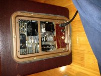
Pictured below are the two guitar inputs at right, and the NFD defeat switch at extreme left. The other control knobs are original.

Enzo, you asked whether it might be a faulty 10MFD cap at the OT secondary to ground position. I happened to do this experiment (unintentionally) earlier along in recapping the amp. I had not ordered enough 10MFD caps the first time around, and substituted a 25MFD cap in that position, (too eager to hear if the amp would work at all). It had the same distortion by ear and on "scope" -- in fact, the first graphics I submitted were with this cap in place. I later switched it for the correct value cap, seen in the second submission. I know this 25MFD cap works, as it is now part of the NFB defeat circuit in the amp, as cathode bypass cap.
I am wondering if this unusual part of the circuit is acting like an automotive ignition, with the cap charging with each crest of the wave from alternate 6V6, and discharging through the transformer if the voltage across the 200 ohm resistor becomes negative. If everything were balanced, and the OT was new, possibly that voltage would never drop below zero. If the "center tap" is not exactly centered on the waveform going through the OT, possibly a negative voltage could briefly appear there. Just speculating, of course.
Here is the schematic before modifications:
And after:
The amp, with the NFB circuit active, but no 10MFD bypass cap in place, sounds good. Maybe that cap was helpful for hifi purposes, but the guitar sound does not seem to be lacking so far. The NFD circuit noticable tightens the base response while cutting the volume a small amount. Without NFD is my slight preference for now, but having both available seems worthwhile for now.
Pictured below are the two guitar inputs at right, and the NFD defeat switch at extreme left. The other control knobs are original.
OK, not the cap itself then. I can't fault the design, I doubt the circuit behaved this way in general, at least within its expected use.
And with that parallel 200 ohm resistor, I have to think that cap is not doing a lot of discharging back into the inductance of the transformer.
BAck about 1968-69, I had a Rickenbacker semi-hollowbody bass guitar and no amp. A little Webcor tape recorder, with its little oval speaker, became my amp for a long while. Absolutely terrible for guitar, let alone bass. But hey, what do you do?
Webcor further tweaking
I have some questions about distortion, particularly about odd versus even order harmonics. This Webcor amp has really turned into my best sounding and most addictive amp to play. Unable to let well enough alone, however, I am wanting to improve its sound from the point where the volume control goes beyond 3:00. At this point, the breakup goes from sweet-sounding to excessively biting and harsh, especially playing high up the neck. This could be musically useful in another guitarists hands, but not exactly what I am looking for.
The full overdriven waveform of the amp looks like:

The waveform transforms from a sine wave to this distortion form fairly abruptly as the volume control increases beyond 2:00. It does not transition through the textbook picture of valve amp soft clipping, with a curved leading and trailing edge and a horizontal plateau. Rather it has a sharp peak, falls away fairly steeply, then more steeply with the trailing edge of the positive sine wave.
The power spectrum for the nonoverdriven and overdriven (full on) regions are:


I can see that the third harmonic becomes relatively higher with overdrive, and odd order harmonics predominate. The distortion here comes from either the phase splitter section or the power section, as bypassing the the 6AT6 gives the same results.
Is the waveform unusual in appearance for an overdriven tube guitar amp? Are there standard ways to adjust the relative contributions of even and odd harmonics in the overdriven range?
I have some questions about distortion, particularly about odd versus even order harmonics. This Webcor amp has really turned into my best sounding and most addictive amp to play. Unable to let well enough alone, however, I am wanting to improve its sound from the point where the volume control goes beyond 3:00. At this point, the breakup goes from sweet-sounding to excessively biting and harsh, especially playing high up the neck. This could be musically useful in another guitarists hands, but not exactly what I am looking for.
The full overdriven waveform of the amp looks like:
The waveform transforms from a sine wave to this distortion form fairly abruptly as the volume control increases beyond 2:00. It does not transition through the textbook picture of valve amp soft clipping, with a curved leading and trailing edge and a horizontal plateau. Rather it has a sharp peak, falls away fairly steeply, then more steeply with the trailing edge of the positive sine wave.
The power spectrum for the nonoverdriven and overdriven (full on) regions are:
I can see that the third harmonic becomes relatively higher with overdrive, and odd order harmonics predominate. The distortion here comes from either the phase splitter section or the power section, as bypassing the the 6AT6 gives the same results.
Is the waveform unusual in appearance for an overdriven tube guitar amp? Are there standard ways to adjust the relative contributions of even and odd harmonics in the overdriven range?
Webcor Harvard/Deluxe update
This is an update to my posts of 2011, on my attempts to make a good guitar amp of a Webcor 166-1 1950's era phonograph amp. I have been able to use this amp in loud situations, holding its own in rehearsal with a drummer and well amplified bass, keyboards and multiple singers.
Many circuit modifications and listening led to the Fender designs of old replacing some of the odd parts of this amp's design. So it can be easily described as exactly a Fender Harvard from the input through the cathodyne splitter, followed by a Fender Deluxe cathode biased output. I installed the usual tone control as found in the Harvard, but then removed it. If you are choosing the coupling caps, that is really the best tone control (once you find the right values). The additional tone control added a veil of muddiness.
But more power is always nice. A 6L6 output transformer (a vintage used one from Ebay, this is all done on the cheap) was added to allow tube experimentation. A switch to bring in the appropriate cathode bias resistors and optimize idle current to specs was added. This arrangement allowed 6V6, EL34, or 6L6 use. Measured output was 14 watts for 6V6, 18 watts for EL34, and 24 watts for 6L6 tubes. Each has different character, can not really pick a favorite. To make sure that there is ample filament current for these tube upgrades, a dedicated filament transformer was added (this from Radio Shack, another inexpensive addition) to meet the higher EL34 specs. And to make the thing run cooler, an AC fan is mounted in the chassis and aimed at the power transformer. Myth has it that Neil Young places a fan behind his 6L6 modded Deluxe, so that is enough technical justification for me.
The chassis of the stock Webcor has a shelf in the back that allowed storage of the microphone cable, but that was removed to enhance air flow. Reflective metal tape was also installed on the transformer, as it is very close to the power tubes and that seemed to be an unnecessary heat problem in the making. After hours of play, the power transformer is now cool to the touch. A small toggle switch controls the fan, in case I want it to run quietly, but I just leave it on.
A very important upgrade is substituting a 12 inch speaker for the 10 inch stock speaker. The stock speaker is a really good sounding alnico with a hifi range, nice but the highs are excessive for a 6 string and it lacks authority. A 12 inch alnico speaker from an old Magnavox console, very inexpensive on Ebay, is really ideal. It is not designed to handle all the power that this amp can deliver, sounds like it could blow at any second, which is to say that it sounds great. At 4 years of frequent loud playing, so far, so good.
Once I did worry that the speaker was too frail, so I installed an Eminence Swamp Thang. It was a very heavy, very loud, very low frequency beast in this cabinet. It did sound good playing alone, and the power was unbelievable. However, playing with other instruments, the cheap, light, alnico cut through much better. A lot more music and less sonic competition with the keyboardist. So that I what I continue to use. The whole amp, with all these mods and the lightweight speaker, is only 24 pounds.
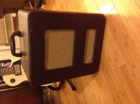
The original speaker cloth was replaced by new Fender tweed style cloth. I think that it looks pretty good.
The control panel, as pictured, from left to right, is now a single input jack, the volume control, the on/off switch, the tube bias selector toggle, a fuse, a modern 3 prong power jack, and a small toggle to control the fan. The speaker plugs in to a jack visible inside the chassis like a conventional Fender amp. Next to that jack is a line out jack.
I think that this amp sounds excellent, is versatile, looks cool, and is super easy to carry around. Thanks to those on this forum that helped me get to this point.
This is an update to my posts of 2011, on my attempts to make a good guitar amp of a Webcor 166-1 1950's era phonograph amp. I have been able to use this amp in loud situations, holding its own in rehearsal with a drummer and well amplified bass, keyboards and multiple singers.
Many circuit modifications and listening led to the Fender designs of old replacing some of the odd parts of this amp's design. So it can be easily described as exactly a Fender Harvard from the input through the cathodyne splitter, followed by a Fender Deluxe cathode biased output. I installed the usual tone control as found in the Harvard, but then removed it. If you are choosing the coupling caps, that is really the best tone control (once you find the right values). The additional tone control added a veil of muddiness.
But more power is always nice. A 6L6 output transformer (a vintage used one from Ebay, this is all done on the cheap) was added to allow tube experimentation. A switch to bring in the appropriate cathode bias resistors and optimize idle current to specs was added. This arrangement allowed 6V6, EL34, or 6L6 use. Measured output was 14 watts for 6V6, 18 watts for EL34, and 24 watts for 6L6 tubes. Each has different character, can not really pick a favorite. To make sure that there is ample filament current for these tube upgrades, a dedicated filament transformer was added (this from Radio Shack, another inexpensive addition) to meet the higher EL34 specs. And to make the thing run cooler, an AC fan is mounted in the chassis and aimed at the power transformer. Myth has it that Neil Young places a fan behind his 6L6 modded Deluxe, so that is enough technical justification for me.
The chassis of the stock Webcor has a shelf in the back that allowed storage of the microphone cable, but that was removed to enhance air flow. Reflective metal tape was also installed on the transformer, as it is very close to the power tubes and that seemed to be an unnecessary heat problem in the making. After hours of play, the power transformer is now cool to the touch. A small toggle switch controls the fan, in case I want it to run quietly, but I just leave it on.
A very important upgrade is substituting a 12 inch speaker for the 10 inch stock speaker. The stock speaker is a really good sounding alnico with a hifi range, nice but the highs are excessive for a 6 string and it lacks authority. A 12 inch alnico speaker from an old Magnavox console, very inexpensive on Ebay, is really ideal. It is not designed to handle all the power that this amp can deliver, sounds like it could blow at any second, which is to say that it sounds great. At 4 years of frequent loud playing, so far, so good.
Once I did worry that the speaker was too frail, so I installed an Eminence Swamp Thang. It was a very heavy, very loud, very low frequency beast in this cabinet. It did sound good playing alone, and the power was unbelievable. However, playing with other instruments, the cheap, light, alnico cut through much better. A lot more music and less sonic competition with the keyboardist. So that I what I continue to use. The whole amp, with all these mods and the lightweight speaker, is only 24 pounds.
The original speaker cloth was replaced by new Fender tweed style cloth. I think that it looks pretty good.
The control panel, as pictured, from left to right, is now a single input jack, the volume control, the on/off switch, the tube bias selector toggle, a fuse, a modern 3 prong power jack, and a small toggle to control the fan. The speaker plugs in to a jack visible inside the chassis like a conventional Fender amp. Next to that jack is a line out jack.
I think that this amp sounds excellent, is versatile, looks cool, and is super easy to carry around. Thanks to those on this forum that helped me get to this point.
Attachments
Sorry I wasn't around for you years ago on this one. Did you ever get your nasty distortion problem under control? I believe you have a biasing problem. Along with some serious gain in the PI and final push-pull stages.
Check out this article. Sections 7 and 9 apply to your power stage directly.
The big dog spike looks like power transformer spiking to me, but it could be one of the plates bouncing against its power supply also.
Check out this article. Sections 7 and 9 apply to your power stage directly.
The big dog spike looks like power transformer spiking to me, but it could be one of the plates bouncing against its power supply also.
Thanks, jeff5may. The spike-in-the-signal problem was solved by removing the C3 10mfd cap, see the schematic in the first post. The amp then had a good sounding overdrive from the volume knob at 1:00 onward. It is fairly clean up to 1:00.
That cap seems to function as a cathode bypass to the power tubes, as well as providing negative feedback. I don't have a good explanation for the spike that it caused.
That cap seems to function as a cathode bypass to the power tubes, as well as providing negative feedback. I don't have a good explanation for the spike that it caused.
C3 in the schematic is your main gain increaser for the power tubes. You said you removed the funky feedback from the speaker winding and connected the cathode bias resistor straight to the cathodes and ground. Without C3 in the circuit, your power section sees the same impedance with both AC and DC components of the signal. The voltage across the resistor starts out at some DC voltage, depending on the current running through the two tubes. When an AC signal is applied, the current through the resistor changes at the same rate. This change tends to lower the voltage between the plate and cathode of the power tubes, decreasing conduction and lowering gain.
With C3 across the cathode resistor, it forms a high-pass filter with the power tubes and output transformer that drastically increases gain above its cutoff frequency. With a large electrolytic cap, this cutoff frequency is less than a dozen Hz, so only turntable rumble and such is attenuated. Above the cutoff frequency, the signal is shunted straight to ground through the capacitor, greatly increasing signal gain.
When the power stage is overdriven hard, the tubes change behavior, and the capacitor helps them along in that direction. That's where your big spike comes into the picture. Being a high frequency component, it isn't limited by the capacitor. The only thing that limits the spike is the output transformer winding and whichever output tube is misbehaving.
I imagine what is happening is that both of the tubes are in cutoff at the point where the spike is initiated. Due to the high slope of the signal at zero-crossing, if both tubes are not conducting, the transformer acts like an ignition coil in a car. With a large change in current flow across the primary winding of the OT, a high amount of counter EMF is occurring due to a rapidly changing magnetic field in the core. When the push-conducting tube stops pushing, and if the pull-conducting tube hasn't yet started pulling, the OT primary sees an open circuit. The counter-EMF in the transformer core dumps into the speaker winding until the pulling tube starts conducting and picks up the slack. Once the tube starts changing primary current at a high rate again, the counter-EMF discharge is stopped and the speaker output goes back to where it was, minus whatever energy made its way out through the speaker(OR BY JUMPING A SPARK GAP SOMEWHERE, WHICH IS BAD ALL THE WAY AROUND).
I don't know how many mods you did to the original circuit, so it is difficult to tell you how to fix the issue. Maybe the PI isn't driving both the power tubes with the same level of grid signal. Maybe your power tubes are not matched. Maybe one grid has a leaky coupling capacitor. There are a number of things that can go wrong, but the loss of balance between pushing and pulling output tubes is most likely the main cause. Since the problem is consistent in nature, measuring AC signals with an o-scope and DC levels with a voltmeter against each side of the push-pull circuit may reveal the imbalance before the "spike" condition occurs. If everything looks kosher while the power section is not "spiking", the problem probably doesn't lie in the phase inverter. If signals don't track well on the grid side of the output tubes, there may be an issue with the phase inverter.
Thanks, jeff5may, that makes sense to me. This amp has progressed quite a bit from the experimental stage that it was in, with the spiking discharge. Needing a guitar amp more than an automotive ignition system, I substituted a "fender deluxe" style power section with standard cathode bias, a larger output transformer, 6L6 capability, a 12 inch speaker. It is a good sounding reliable amp that I use every day. I sold my only other amp, it is really that good.
But, I am starting another amp project, so I will probably have more puzzles to present on this forum. Briefly, it is a single ended conversion of an old extension speaker, featuring a 6C8, 6L6, 5Y3, 8 inch field coil Rola, and battered tweed cabinet. Currently recapped and passing a signal, will need more work. Will post when there is more to say. Thanks for the expertise.
But, I am starting another amp project, so I will probably have more puzzles to present on this forum. Briefly, it is a single ended conversion of an old extension speaker, featuring a 6C8, 6L6, 5Y3, 8 inch field coil Rola, and battered tweed cabinet. Currently recapped and passing a signal, will need more work. Will post when there is more to say. Thanks for the expertise.
Sweet... I love hearing about people keeping these vintage beasts breathing. Gone are the days of people everywhere tinkering with electronic devices on benches. Modern "common" equipment is simply disposable compared to the "ancient" stuff in every way.
Keep up the good work. Share what you can. This is a dying art.
Keep up the good work. Share what you can. This is a dying art.
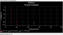
Thanks, jackinnj, for noticing that, and for running the simulation. I think that you did spot a problem on the most recent schematic in my post. I'm not sure why I used 250R for the 6AT6 at that point in time. I recall that I did substitute a 1500R there, based on copying a Fender Harvard use of that tube. Not as elegant as simulating, of course. I recall tracing the signal on my Mac oscilloscope, and this tube was passing a clean waveform long after everything following was clipping. I'm not very educated about this tube, but have considered it to be a special secret ingredient that helps this amp sound different than all the others. Some magical thinking, no doubt. I should look into doing simulation (your post convinced me) any suggestions for Mac based programs?
- Status
- This old topic is closed. If you want to reopen this topic, contact a moderator using the "Report Post" button.
- Home
- Live Sound
- Instruments and Amps
- Webcor conversion, odd distortion