Ok, so now that the hum balance and tape head bias circuits are no longer in circuit, I have 3 free 2 megohm pots to put to use. I'm assuming I can sub any of these into the existing circuits in place of the old grid leak resistors, mainly R12. I also have a tone control further down the audio path that is 1 megohm, and is on the sleeve that surrounds the shaft of the volume knob. I believe this would be ultimate: preamp drive surrounding master volume knob. Which begs more questions:
How many components can I lose between R12 and V1-A? Rather, Which of these, besides the plate current source, R11, do I really need?
What components do I really need in the tone control on the other side of the phase inverter? Can I just disconnect the pot and leave the rest?
If I get much more signal through to the power stage, this rig will leave the realm of a "bedroom amp". With the 6k6 tubes in the output sockets, none of the iron is being stressed at all. However, if and when my son decides to roll some 6v6gt or 6p6s or 7408 through this machine, it should hold up and punish the ears. As it is now, it walks the line between "annoying" and "too loud" pretty well.
Those 2Meg pots are too large. They should be 1Meg audio taper. 1Meg is the largest value allowable for 12AX7s for the grid leak value. Yes, where the grid leaks are where the vol. control is at.
I would be tempted to lose all the components between R12 and V1a except the coupling cap and the plate resistor. Most of these are for tone shaping, so be ready to change the coupling cap if you don't like the sound.
As far as power, the 6k6s will be 10watts and 6V6s will be around 15 watts, only a difference of 1.8dB. Hardly enough to hear. If you like the sound and you don't want to have 1Meg grid leaks, leave them at 470K. I thought i saw a referral to the sound of a "blade cutting metal" as the goal. You can get that with power amp distortion. If you only get distortion with the preamp, it tends to be buzzy and thin.
As far as the components for that tone control Post Phase Inverter, just a pot and cap in series between the wires going to the grids of the 6K6s connected after the coupling caps.
Here is a schematic for a Matchless Spitfire and a PPIV volume control. Put a .0047u(470pF) cap in series with the pot and you have a PPIV tone(cut) control. If it doesn't sound right, try different cap values.

Last edited:
Boobtube,
Thank you so much for your assistance and guidance. I have the theoretical and construction experience behind me, but not much practice with pro audio. I have repaired a few units for friends, just they were all solid state. The quick and concise answers have certainly helped this project and gave me insight into these classic units. I knew they were simple in design, but not so minimal in component count.
Once we take all the extras out, we will push these tubes to see if he likes the distortion. If the thing needs an attenuator, it can be added in.
Attenuation can be accomplished very easily with lower value grid leaks on inputs or voltage dividers on the output of the stage. Also, the easiest way is to use lower amp. factor tube. Sub in a 5751 for a 12AX7. This drops the mu by 30 for each triode. Also using one 7247 when stages are cascaded lowers one stage from 100 down to 20. The other is kept at 100. Another way is to decrease the plate load resistor from 100k to 82k or a little less. This causes less signal swing and gain, but more distortion. Can you post a schematic showing the changes you have made so far? It seems as though you are coming along nicely with this. Great project!
I stopped by a local parts house on my way home from work today, looking for op amp chips and discrete components. The owner and I had some discussion on the current local market. Apparently, there is none. His biggest sellers over the counter are tools and zip ties. He told me to go fish, radio shack might have something if they haven't closed their doors yet. I know the electronics service industry has taken a beating since 911, but now there are no real parts houses left in the Louisville metro area. When I asked him about vacuum tubes, he told me to find ham radio operators. Apparently they are also a dying breed.
I found something I was looking for at the shop. He had power resistors on clearance for a dime each. I now have a dozen 25 ohm, 30 watts in my possession. I might go back tomorrow and buy the whole box. Either way, I found my attenuation network.
I found out today that the radio shack by my place closed is doors this month.
Last edited:
There's plenty of places online to buy stuff. Here is where I get mine:
www.tubesandmore.com, If you need thousands of each part, Mouser has anything you will ever need. I like mine because they carry a great selection and have the most commonly used parts. Its sister site is Amplified Parts. Between these two, you should be able to get what you need.
www.tubesandmore.com, If you need thousands of each part, Mouser has anything you will ever need. I like mine because they carry a great selection and have the most commonly used parts. Its sister site is Amplified Parts. Between these two, you should be able to get what you need.
I will post up a schematic when I get the thing running well. I gutted most of the strangeness ot of the first two stages. Now there is an imbalance in the phase inverter. The bottom half has more signal than the top. We may end up getting the nonsense out of it also. I don't like his the bottom half feeds off the top half output.
I thought I would make a progress post about this project.
While the amp was still in the original chassis, we tried a whole bunch of configurations. The preamp used both of the triodes in the first tube. The two stages were rigged up pretty much like the matchless schematic, with a gain pot in between the two common-cathode stages. Once the two preamp stages were straightened out, they had way more gain than the PI could handle. Even with a big grid blocker and teeny coupling cap to shape the signal, the blocking distortion could not be tamed.
The next thing we did was to gut the PI as it was originally wired. To do this, I stuck a 12AU7 in the PI socket and wired it to the output transformer. This way, we could actually hear what the tube was doing as we applied changes. It took awhile, but we finally got the section sounding right. I did a load-line analysis and rigged the tone circuit in from the original chassis. It didn't sound half bad the way it was, but after using it for awhile, my son found it did not have enough output power to get that modern metal "chugging" sound out of it. So we rigged it up as a long tail pair, and stuck a 12AX7 in the socket for more gain.
The original power stage was run ultralinear using feedback from another winding of the output transformer. When first wired back into the circuit, the factory power amp acted strangely. It went from super clean and sterile to ugly and compressed at not much more volume than the 12AU7. The output waveform was lopsided when this happened, probably from the output tubes not being well matched. So we ditched the transformer feedback and ran the cathode resistor to the center tap of the primary winding.
At this point, we left the thing in its somewhat modded state, and I let my son play with it for awhile. If he wasn't picky, we probably could have left the thing the way it was. Minor changes in components for voicing, build a box around it, done. It was plenty loud enough for a bedroom (or garage), and got to that AC/DC crunchy distortion. With pedals in front of it, the thing didn't do half bad. But he wasn't happy with it, not enough knobs. So we ordered some parts and started on a new chassis...
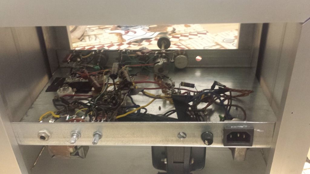
So we made a parts order. I got some ceramic tube sockets, two used sovtek 12AX7 tubes(with egnater logos), a few volume pots, some knobs, and resistors. I found a piece of galvanized wall stud channel and cut it to length. Grabbed some step drill bits from harbor freight and drilled holes. We put 4 preamp tube sockets in in and played around with gain stages to try to get the sound he wanted out of the amp, again wired with a 12AU7 running push-pull into the stock webcor OT. I believe we used a 500 ohm cathode resistor with no capacitor bypass. FWIW, the OT has a center tapped 10K primary, a 40 ohm feedback winding, an 8 ohm speaker winding, and a 500 ohm line out winding.
After plenty of tinkering, the chassis had too much gain for the sound he was looking to get. Three preamp tubes was more than enough to get the screamin' lead or EVH sound out of the speaker. That's not the sound he was looking for, though. So I wired up a bridge rectifier between the second and third stages to get the thing to clip the way he wanted it to. It sounded closest to what he wanted out of the high-gain configuration if an LED was wired to the DC output of the bridge. I can't remember if he liked a blue or red LED better, but after playing it for awhile, it still didn't sound right. It didn't like pedals as well with 3 preamp tubes either, and the more amp stages we added, the more muddy and blurred the signal became. At a certain point, the preamp lost its definition and clarity, replaced with sludge and compression. So we went back to the original setup, with a single tube preamp (2 gain stages) and the long-tail pair PI.
At this point, we wired in a TMB tone stack and master volume between the preamp tube and PI. The power tube sockets were removed from the original chassis, and the feedback windings were removed from the circuit. The 6K6 tubes were wired with cathode bias, with a 390 ohm cathode resistor. We settled on a 100 uF bypass capacitor. Feedback was rigged by tapping the speaker output winding and fed back into the phase inverter, marshall style.
We added presence and resonance controls to the negative feedback loop. We started out with the EVH 5150 circuit, then tweaked values to get the right contour out of the loop. I believe the presence and resonance controls ended up close to the values in the PV 6505 head, but not exactly. For what was in there, the 6505 circuit had too much negative feedback, and reduced the maximum output of the power amp section too far. Adding a resistor in the feedback line brought the output level back up,but changed the crossover frequencies of the controls. A good amount of tweaking capacitor/resistor values and live testing was done to get good performance out of the controls.
A cabinet was built out of aluminum extrusions to house the chassis. It's not completely finished yet. I bought some scrap pieces of anodized aluminum channel from work, originally used for handicap ramp and stairwell stringers in sports stadiums. Mitered the corners on a table saw and riveted the box to vertical angles at the front and rear corners. The chassis will be fitted to these angles to be super solid, and the top will have screws that can be removed to take the chassis out the top for whatever it might need later.
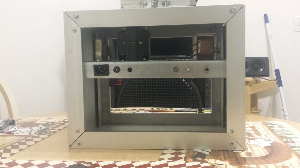
The presence and resonance controls are next to the speaker jack. The open hole is still to be determined: it might be a standby/power switch, or it might be one of two jacks for an effects loop or footswitch.
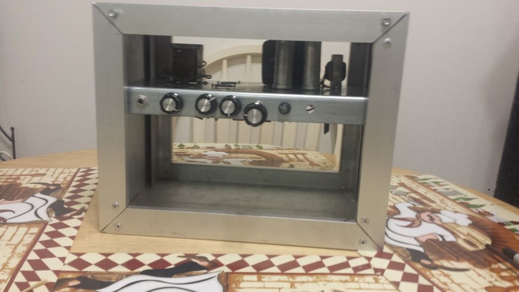
The open hole is for the extra pot in the TMB stack. Currently, the stock pot for tone and volume is used for bass and treble. The pot without a knob is the mid sweep control. New pots are on the way.
A cover for the bottom of the channel will be made to cover everything once we are done modding this thing. It will fasten to the side rails.
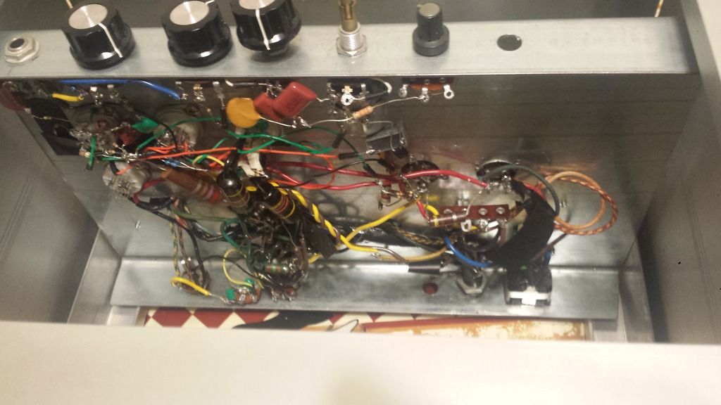
All the sloppy point to point connections will end up connected to some tag strips from the original chassis once we are done fiddling with values.
After plenty of tinkering, the chassis had too much gain for the sound he was looking to get. Three preamp tubes was more than enough to get the screamin' lead or EVH sound out of the speaker. That's not the sound he was looking for, though. So I wired up a bridge rectifier between the second and third stages to get the thing to clip the way he wanted it to. It sounded closest to what he wanted out of the high-gain configuration if an LED was wired to the DC output of the bridge. I can't remember if he liked a blue or red LED better, but after playing it for awhile, it still didn't sound right. It didn't like pedals as well with 3 preamp tubes either, and the more amp stages we added, the more muddy and blurred the signal became. At a certain point, the preamp lost its definition and clarity, replaced with sludge and compression. So we went back to the original setup, with a single tube preamp (2 gain stages) and the long-tail pair PI.
At this point, we wired in a TMB tone stack and master volume between the preamp tube and PI. The power tube sockets were removed from the original chassis, and the feedback windings were removed from the circuit. The 6K6 tubes were wired with cathode bias, with a 390 ohm cathode resistor. We settled on a 100 uF bypass capacitor. Feedback was rigged by tapping the speaker output winding and fed back into the phase inverter, marshall style.
We added presence and resonance controls to the negative feedback loop. We started out with the EVH 5150 circuit, then tweaked values to get the right contour out of the loop. I believe the presence and resonance controls ended up close to the values in the PV 6505 head, but not exactly. For what was in there, the 6505 circuit had too much negative feedback, and reduced the maximum output of the power amp section too far. Adding a resistor in the feedback line brought the output level back up,but changed the crossover frequencies of the controls. A good amount of tweaking capacitor/resistor values and live testing was done to get good performance out of the controls.
A cabinet was built out of aluminum extrusions to house the chassis. It's not completely finished yet. I bought some scrap pieces of anodized aluminum channel from work, originally used for handicap ramp and stairwell stringers in sports stadiums. Mitered the corners on a table saw and riveted the box to vertical angles at the front and rear corners. The chassis will be fitted to these angles to be super solid, and the top will have screws that can be removed to take the chassis out the top for whatever it might need later.
The presence and resonance controls are next to the speaker jack. The open hole is still to be determined: it might be a standby/power switch, or it might be one of two jacks for an effects loop or footswitch.
The open hole is for the extra pot in the TMB stack. Currently, the stock pot for tone and volume is used for bass and treble. The pot without a knob is the mid sweep control. New pots are on the way.
A cover for the bottom of the channel will be made to cover everything once we are done modding this thing. It will fasten to the side rails.
All the sloppy point to point connections will end up connected to some tag strips from the original chassis once we are done fiddling with values.
OK, so another update:
My son has been playing the heck out of this unit for a few months, and still prefers it over just about anything that doesn't cost more than a thousand dollars. He has decided that it doesn't need to be as tall as it is, so we will be turning it into a more true "lunchbox" amp, chopping maybe 3 inches off of the overall height.
The layout is very much like this:

Main differences being:
-solid state rectifier in power supply
-presence/resonance controls via global negative feedback
-300 to 315 VDC supply voltage
-6K6GT output tubes
So now that I thought we were about done tweaking this thing, he bought some 6V6GT tubes (matched pair of Tung-Sol NOS) to try out in the chassis. He has caught the virus, and wants to squeeze more power and headroom out of this chassis for what these new valves can offer. Problem is, the new 6V6 tubes have MUCH more gain than the 6K6 tubes (gm of 4200 vs. 2600), and simply swapping bottles yields a bass-heavy beast that cannot be tamed by the TMB stack.
For the moment, I swapped the PI (12AX7) for a 12AU7 to both provide lower source impedance for the 6V6 stage and less voltage gain. I also stuck a bright cap on the pre-gain control to let more highs through at lower knob settings. This has tamed the chassis somewhat, so he can get a feel for the new valves. But the chassis acts completely different with the 6V6 valves in the sockets.
As the master volume knob approaches noon or maybe 1 o'clock, the whole amp breathes and compresses badly. I haven't taken any scope readings yet, so I'm not completely sure which stage is the culprit here. Can someone help me out here? I know the power supply isn't drooping when this happens: are the 6V6 tubes being starved for power, or being overdriven badly?
My son has been playing the heck out of this unit for a few months, and still prefers it over just about anything that doesn't cost more than a thousand dollars. He has decided that it doesn't need to be as tall as it is, so we will be turning it into a more true "lunchbox" amp, chopping maybe 3 inches off of the overall height.
The layout is very much like this:
Main differences being:
-solid state rectifier in power supply
-presence/resonance controls via global negative feedback
-300 to 315 VDC supply voltage
-6K6GT output tubes
So now that I thought we were about done tweaking this thing, he bought some 6V6GT tubes (matched pair of Tung-Sol NOS) to try out in the chassis. He has caught the virus, and wants to squeeze more power and headroom out of this chassis for what these new valves can offer. Problem is, the new 6V6 tubes have MUCH more gain than the 6K6 tubes (gm of 4200 vs. 2600), and simply swapping bottles yields a bass-heavy beast that cannot be tamed by the TMB stack.
For the moment, I swapped the PI (12AX7) for a 12AU7 to both provide lower source impedance for the 6V6 stage and less voltage gain. I also stuck a bright cap on the pre-gain control to let more highs through at lower knob settings. This has tamed the chassis somewhat, so he can get a feel for the new valves. But the chassis acts completely different with the 6V6 valves in the sockets.
As the master volume knob approaches noon or maybe 1 o'clock, the whole amp breathes and compresses badly. I haven't taken any scope readings yet, so I'm not completely sure which stage is the culprit here. Can someone help me out here? I know the power supply isn't drooping when this happens: are the 6V6 tubes being starved for power, or being overdriven badly?
I have some 6K6's running at 350V or there about. 6V6's at 300, well I guess you could. I would expect they are deep in class A territory. You could try biasing the preamp tubes cold, maybe 2.7k for the first stage. Heck, up to 10k for the next stage since you seem to have some gain to loose. See how that sounds. On the PI, the values in the schematic are very EL84'ish. Drop the 47k in half. Should give the stage some headroom.

That's a very odd design. Turn down the volume and you also progressively remove the bass (because those 0.022 uF coupling caps are now working into a smaller resistance).Here is a schematic for a Matchless Spitfire and a PPIV volume control.
View attachment 479322
Doesn't that seem exactly backwards? Our ears hear bass worse at low volumes, which is why loudness controls boost the bass (and treble) at low volume settings to compensate.
I wonder if this was an attempt to produce a PPIMV using a single pot (instead of a dual-ganged one), and the person who came up with this approach did not notice the unwanted effect on bass response?
-Gnobuddy
More refinements have been done to the rig. We are back to using two 12AX7 tubes for the preamp and phase inverter. I did some tweaking and re-re-rigging of stages to ame them some. The 6V6 outputs are comfortable in their sockets now.
I would have had a really good schematic drawn up today if Ltspice wasn't such a pain in the butt. I have used a fair amount of apps to draw up prints and schematics in the past, and all the veteran posters are all about spice sims, so I thought why not. Hours later, and I have yet to find any decent templates that represent common things.
Examples are as follows:
6V6GT (correct symbol with lib/mod file)
18Watt-style power or output transformers (or a symbol for the Heyboer HT-whatever that Jazbo posted a subckt file for previously)
Standard value potentiometers (linear and log)
I'm sure all the pro's have a secret stash of library on hand to pilfer through, or have actually conjured up heir own symbols, assemblies, and models. I am doing this in my spare time as a DIY hobby project. I would think that someone somewhere selling these components would have this info somewhere that would be easy to find or figure out, but no. Apparently, reinventing the wheel and mousetrap every time you need to is common practice. Either that, or the prefab symbols and such aren't free.
So I ran out of time trying to figure out details for part simulations I couldn't find. Can someone help me out here?
The two transformers I have in this thing are:
PT: Webcor 68p028-5 aka Stancor PC-8418
Primary: 117VAC@400mA
Sec#1: 450VCT@50mA
Sec#2: 12.6VCT@2.6A
OT: Webcor 67p050-2
Zprimary = 9.5K ohms
Zsecondary = 8 ohms
(other windings ignored)
This is as far as I got today. Change the attached file to asc filetype to see it in Ltspice. The project ate into my alone time with my wife today, so I shelved it in a heartbeat. Please help me out here, experts.
Attachments
Last night while I was sleeping, my son was playing murder death warfare arena, league of legends, playing guitar through some sennheisers, and looking for something that would go in the schematic. He went to sleep a short time before I woke up, and left me a few tidbits on the screen. Gotta love the new generation.
I found this thread, and an output transformer that looks great from a few paces away. Ugt's zip file seems OK from here, now I just have to figure out how to copy that crap from one schematic and paste it into another (if possible - grumble).
:: View topic - Drop down transformer models for LTSpice
Way to go!
You're an excellent teacher, and your son is lucky to have you for a dad!
-Gnobuddy
I love the way you approached this. Let him find what he likes, then help him understand it. What a great way to help you son not only enjoy one of his passions, but also learn a lot along the way!Rather than leave him to spend thousands of dollars and years of his time, I'm going to set him up with some knowledge and a test bed of a studio/bedroom amp.
You're an excellent teacher, and your son is lucky to have you for a dad!
-Gnobuddy
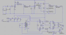
I got half a facsimile of the amp kinda drawn up on Ltspice. How do u like it?
Still looking for a spice model/assembly/object for a power transformer.
http://cds.linear.com/docs/en/lt-journal/LTMag-V16N3-23-LTspice_Transformers-MikeEngelhardt.pdf
Solutions - LTspice: Simple Steps for Simulating Transformers
LTspice Transformer Library, Transformer design, Flyback transformers | Wurth Electronics Midcom
Over 200 Power Transformers | Free LTspice Transformer Simulator
http://web.cecs.pdx.edu/~tymerski/ece222/How to create a transformer using LTSpice.pdf
Spice Component and Circuit Modeling and Simulation
That should be enough for now.
Thanks for the guidance and words of encouragement everyone. I believe we are pretty well done with the overall design of this rig. All that is left are minor voicing refinements, mostly in the EQ and presence/resonance sections. After that, we will make it look pretty. Thanks to all the input from members, this turned out much better than I expected it would.
My son likes this little amp better than his SS Randall 212 combo amp, as well as a whole lot of other amps on the market. He has gained a new appreciation for the little "champ amps" and is now auditioning them at guitar shops along with other "ancient" full-size heads, and not much else. He has gotten pretty darn good with a soldering iron and common instrumentation in a relatively short time, and has lost the overwhelming fear of blowing something up messing with it. He is doing parts swaps and trials himself now, which is a good thing. It looks like I'll be working 7 days a week until Christmas or later, so I won't be having much time to invest in the project for a long while.
Once this is declared finished, I'll post pics and an updated schematic. Thanks again, everyone.
- Home
- Live Sound
- Instruments and Amps
- Webcor 2611 morph into practice amp