My son and I are going to build his first ever tube powered guitar amp. He has a ss line6 spider 4 75 that he uses to play with the band with now that keeps up with the drummer. It models gobs and tons of different sounds kinda ok. However, like most midi/ss amps, it just can't deliver that tube amp sound. It is too loud for his bedroom, where he studies and plays his computer and guitar most of the time. We whipped up a little op-amp/ss chip amp at first, but it is too dry, and doesn't have that "tube sound" when it distorts. And guess what? He likes bluesy "crybaby" sounds and "metallica" heavy metal distortion.
We went to guitar center so he could figure out what he likes in tube amps, and the results surprised me. Contrary to my assumption that he would be drawn to the mesa/marshall amps, he has gravitated towards the vox and orange amps. Between the ac30 and the tiny terror, he probably spent an hour going back and forth. He could not pick a favorite, the vox sounded better clean and the orange sounded better distorted. When pushed into a choice, he said he would take the vox and add pedals if he had to choose. But it was too loud.
We went to guitar center so he could figure out what he likes in tube amps, and the results surprised me. Contrary to my assumption that he would be drawn to the mesa/marshall amps, he has gravitated towards the vox and orange amps. Between the ac30 and the tiny terror, he probably spent an hour going back and forth. He could not pick a favorite, the vox sounded better clean and the orange sounded better distorted. When pushed into a choice, he said he would take the vox and add pedals if he had to choose. But it was too loud.
Last edited by a moderator:
Marshall valve state amps use a few 12ax7's to generate the tube sound.
It might be worth looking up the circuit diagram for a Marshall AVT150 valve state 2000.
It only uses tubes in the pre amp stage.
It might be worth looking up the circuit diagram for a Marshall AVT150 valve state 2000.
It only uses tubes in the pre amp stage.
Armed with this info, I started hunting for an old chassis we could mod into a below-10-watt guitar amp we could build up on the bench. What I found was a Webcor 2611 Royal reel-to-reel tape deck that a previous owner was parting out. The cabinet was not well cared for, and the rubber was rotten in the transport mech, but it would make sound from the mic input. The owner had done some googling and had heavenly prices attached to the tubes in the set, so I ended getting just the chassis. I hope he gets close to what he wants for those old bottles.
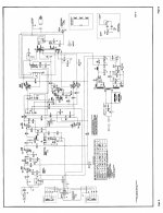
The original design has a 12ax7 up front for two stages of preamp gain, a passive volume/tone knob, and another 12ax7 for a phase splitter. The output stage has 6V6GT tubes running push-pull into an OPT that has four windings. The main primary is 11k plate-to-plate, center tapped. The "other primary" is 40 ohms and runs cathode feedback to the output stage. The two secondaries are 8 ohms (speaker out) and 500 ohms (line out). The original output circuit also does double duty, exciting a bias oscillator for recording mode. It uses a 6x5 running a lcrcrc power supply.
When we first got the chassis, we didn't have any output tubes or a rectifier. I found some 1n4001 diodes, running 2 in series on each leg of the PT. I rigged the phase splitter stage straight to the OPT, so my son could roll tubes with it and get a general feel for the initial sound and circuit. In this configuration, a 12ax7 could not drive the OPT to a level higher than about 3 o'clock on the volume knob without getting mushy in the phase splitter socket. It was quickly swapped out for a 12au7. We also tapped the signal at each stage for him to run into a PA, so he could listen to each stage and how it compared to the final output.
Once we got the original chassis up and running, he started rolling tubes in it and comparing sounds at each stage as well as the raw output. He is running the patient into either a peavey xm-4 PA (line level) and a 15" monitor or straight into the other identical 15" monitor. Since the 12au7 tubes are wider in their variance than their -ax7 brothers, he has been busy rolling through my stash and finding out what he likes and doesn't in the various models. He quickly gravitated to an RCA clear top for the front-end socket.
I started looking for output tubes that are comparable to the 6v6gt, but may swap with the usual suspects for somewhat reduced output power. If he wants to roll output tubes, he has been shown how to measure and adjust the cathode resistor so the tubes are biased correctly. I found a matched set of 6k6gt bottles on ebay for 10 bucks shipped to get us going on the outputs.
I found a schematic for the unit, circa 1956. Here it is:
Attachments
Marshall valve state amps use a few 12ax7's to generate the tube sound.
It might be worth looking up the circuit diagram for a Marshall AVT150 valve state 2000.
It only uses tubes in the pre amp stage.
Yes, my son has decided he likes the other way better. Line6 makes a spider valve amp, which basically has a DSP card for a preamp and 6l6 output tetrodes. Unfortunately, it is a ways down that bottomless abyss that is the perfect guitar amp for the money. Not enough to break you, but more than I am willing to pay, and WAY more than he can afford. He has begun to feel the dark side calling him to abandon his responsibility and indulge in the next best thing ever.
I brought him off the ledge with that model by having him try some pedals with it. Apparently, many of the modeling guitar amps don't like to be connected to anything other than a guitar. A microphone or pedal on the input just confuses the DSP or something. A super-duper rat metal pedal made the thing sound like an AM radio that was mic'ed into something way too loud. But he still has it in the back of his head that he could get it JUST to play guitar with. Then he could rule the galaxy with the spider valve!
I'm not exactly following, have you given up on the Webcor?
You could put something like 5881s in it and switch to fixed bias to get the most power possible. Would that make it useful to him?
My son also has a Line 6 and bought a used Fender Hot Rod Deluxe reissue that is mostly tubes, OP amps in the reverb path. He says the Fender doesn't seem right and I've just started looking at it, it doesn't look old but we think it is from 1996, so almost 20 years old. Paint on the output tubes is so badly discolored that it looks like they've been most likely red plating.
He thinks that once it is working right, pedals in front of it are going to get him the sound that he wants. Also, it is way too much power for practicing even small shows so we plan to add half and maybe 1/8th power soak on the output.
He mentioned how many professionals play through a fairly small 15 - 20W amp with a single 12" speaker so that they can push it very hard and then just mic it through the PA. This probably makes a lot more sense for most.
This is mainly about studio recordings where they want even less power:
http://www.gibson.com/en-us/lifesty...arandinstruments/10-huge-sounds-recorded-521/
Last edited:
I'm not exactly following, have you given up on the Webcor?
You could put something like 5881s in it and switch to fixed bias to get the most power possible. Would that make it useful to him?
My son also has a Line 6 and bought a used Fender Hot Rod Deluxe reissue that is mostly tubes, OP amps in the reverb path. He says the Fender doesn't seem right and I've just started looking at it, it doesn't look old but we think it is from 1996, so almost 20 years old. Paint on the output tubes is so badly discolored that it looks like they've been most likely red plating.
He thinks that once it is working right, pedals in front of it are going to get him the sound that he wants. Also, it is way too much power for practicing even small shows so we plan to add half and maybe 1/8th power soak on the output.
He mentioned how many professionals play through a fairly small 15 - 20W amp with a single 12" speaker so that they can push it very hard and then just mic it through the PA. This probably makes a lot more sense for most.
This is mainly about studio recordings where they want even less power:
10 Huge Sounds Recorded on Small Amps
No, we haven't given up on the webcor conversion at all. He is using it as it is now, running a fraction of a watt of output through the 12au7 phase inverter section. It's not loud enough for his bedroom, but he is getting some play time in while sampling a variety of (no longer new) old stock tubes. Once the power tubes make their way here, they should plug right into the output sockets after some quick and dirty jumper wires are removed.
The Line 6 has now found a home in the practice garage at drummer buddy's place. It does just fine for him as a practice amp in the garage. When he started seriously playing guitar, he settled on the solid state 75 combo, since it did all the gimmickry that the separate head has. Rather than lug around a head and a cab, or have 2 cabs, he got the combo.
He has had the combo for a few years now, and the amp is actually still being used regularly. That in itself with kids nowadays speaks for itself. He has mastered the "modeling menu" of the pod/pedal section, and can quickly make the amp sound almost just like "the other guy's" pedal board and whatever he's got. I'm still amazed he can rig this thing to a pc and upload or download custom effects that used to cost a thousand dollars. He has the thing programmed full of presets he likes, and still tweaks with them on the computer and with the onboard knobs and buttons occasionally. But he has become familiar with its limits.
As you all know, vacuum tube circuits are simple in comparison to the modern digital circuitry and software found in modern guitar amplifiers. Also, they have certain properties that are difficult to reproduce faithfully with solid state circuitry. These behaviors and personalities are easy to recognize when witnessed. My son has had a few of these moments and wants to pursue a quest to find the holy tube tone.
Rather than leave him to spend thousands of dollars and years of his time, I'm going to set him up with some knowledge and a test bed of a studio/bedroom amp. If he wants to use it for a bedroom amp, he can find the ultimate pair of 6k6 and 9-pin triode tubes for it. Maybe he and his buddies can do some mad science projects with it. If it needs to be loud, he can stick some 6v6 bottles in it. With an output xfmr upgrade, the chassis will probably run some 6l6's or kt88's, since the tube recto won't be robbing the mains xfmr. It might only put out 30 watts, but that's not my problem. The thing will be made for 10 watts or whatever the webcor chassis can muster.
I wrote that my son got a Fender Hot Rod Deluxe, actually it is the Hot Rod Deville reissue with four 10" speakers, way more than he needs but he says it just doesn't sound right.
I'm seeing decent looking old production 6V6s used for not too much on ebay. You could go with something like 12V6s if you don't mind wiring up 12 volt heaters. They are much cheaper.
I'm seeing decent looking old production 6V6s used for not too much on ebay. You could go with something like 12V6s if you don't mind wiring up 12 volt heaters. They are much cheaper.
I have a feeling we might have a hard time making the outputs distort gracefully. This thing has lots of feedback paths.
You can always remove the feedback paths.
Did you notice this thread, you might get some ideas:
http://www.diyaudio.com/forums/instruments-amps/190738-hundred-buck-amp-challenge.html
Did you notice this thread, you might get some ideas:
http://www.diyaudio.com/forums/instruments-amps/190738-hundred-buck-amp-challenge.html
You can always remove the feedback paths.
Did you notice this thread, you might get some ideas:
http://www.diyaudio.com/forums/instruments-amps/190738-hundred-buck-amp-challenge.html
Yes, I have been reading it off and on for a few days. Still have a long way to go, though. I'm on page 13. Tons of useful ideas and information, as well as suppliers.
My favorite quote so far:
"Congratulations you have out cheaped me, a truly amazing achievement!"
OK, so the tubes came in the mail today. Unpacked them and un-rigged the phase inverter from the output transformer. Plugged in and turned on, waited 15 seconds, and we have sound! one problem, though: not enough gain for my son. Even with 2x 12ax7 bottles, the amp is just too clean. Not all that bright, even with the tone knob dimed. When it does distort, it's not the desirable kind. Sounds like too much low end is hammering a stage into fart and slobber zone.
A quick swap to a 12au7 in the phase splitter socket gets rid of the blap flap fart mode. But still not enough brightness or gain. I believe running silicon rectifiers has beefed up the power supply, as well as not running the "magic eye" or tube recto heaters. As a result, I have gained a considerable amount of headroom. Any suggestions with what I have running to get some more dirt?
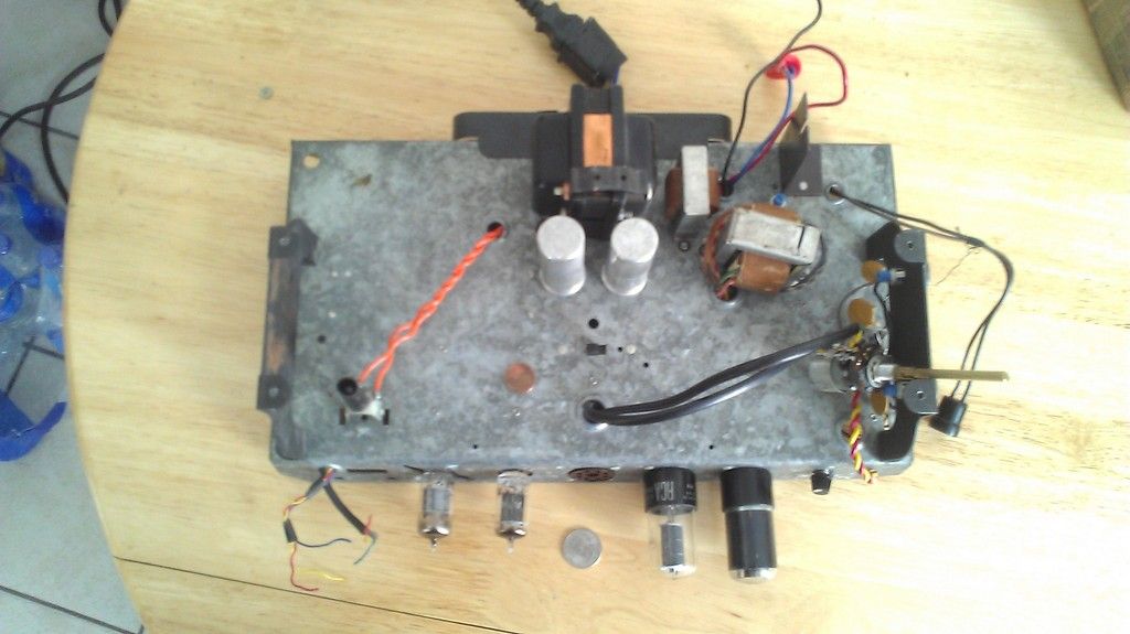
What a matched pair! I got an RCA blackplate and a smoke super silvertone! As long as they draw close to the same idle current, it can only add character... whaddya expect for ten bucks shipped? At least I didn't get metal cans (they are both GT's). I'm going to start taking readings and removing useless crap from the chassis now, namely the bias oscillator and "magic eye" level detector and remote socket wiring. And the tape head wires, and...
A quick swap to a 12au7 in the phase splitter socket gets rid of the blap flap fart mode. But still not enough brightness or gain. I believe running silicon rectifiers has beefed up the power supply, as well as not running the "magic eye" or tube recto heaters. As a result, I have gained a considerable amount of headroom. Any suggestions with what I have running to get some more dirt?
What a matched pair! I got an RCA blackplate and a smoke super silvertone! As long as they draw close to the same idle current, it can only add character... whaddya expect for ten bucks shipped? At least I didn't get metal cans (they are both GT's). I'm going to start taking readings and removing useless crap from the chassis now, namely the bias oscillator and "magic eye" level detector and remote socket wiring. And the tape head wires, and...
Last edited:
Look at a similar Fender schematic and downsize the coupling caps to roll off the bass.
Add cathode bypass caps to the pre amp stages to get more gain, etc.
Put a feed forward cap on the volume control to make it brighter - or get a better speaker.
Reduce the amount of negative feedback.
Took a look at the schematics, the output plate supply was only 240V? I'm running 6V6s at
340V and that is low. I seem to recall Fender going to 400V in one of their amps and many
of the better 6V6 GTs will take it. Look up Tubelab on here, he had 6V6s at 500V I think, lol!
You could lift the ground on the center tap and go full wave bridge, then you'd have too much
so drop it down perhaps with a 10W resistor.
Edit: resistor dropping the supply is not really practical since the caps will see full voltage until
the output warm up and draw current. FET voltage regulator?
The pre amp stages are also running very low and have no cathode resistor, 1.5K there is
typical, and try to get the plate supply up to 300V on the top of the plate resistor.
Remove the feedback to the cathode of the first stage.
I don't think 4.7M grid leaks are allowed in the RCA specs, this might have been designed before
the 1M limit came out, but I'd drop it to 1M.
I think that there is hope for it!
Last edited:
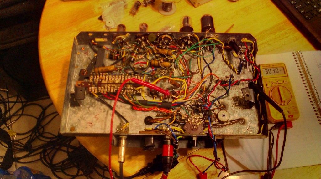
With the 1 amp silicon rectifiers, I am seeing around 340-350 VDC B+ at startup, falling to around or a little above 300 V when the tubes kick in. This is the plate supply. The preamp stage is seeing around 300 VDC, falling to 230 V or less when the screens start drawing juice. I have tied the plates and cathodes to where they belong, rather than through the switch bar of doom. The bias oscillator xfmr is now out of circuit, as well as the socket and leads for the magic eye tube. I also lifted the cathode resistor from its 40uF shunt, which brightened up the output a whole lot. The 270 ohm cathode resistor is dropping exactly 13 V with no input, which calulates to 48mA split between the two output tubes. I read someplace the 6k6 like about 25mA each when run class AB, what do you all think? It seems I am headed in the right direction. Comments welcome.
Look at a similar Fender schematic and downsize the coupling caps to roll off the bass.
Add cathode bypass caps to the pre amp stages to get more gain, etc.
Put a feed forward cap on the volume control to make it brighter - or get a better speaker.
Reduce the amount of negative feedback.
Took a look at the schematics, the output plate supply was only 240V? I'm running 6V6s at
340V and that is low. I seem to recall Fender going to 400V in one of their amps and many
of the better 6V6 GTs will take it. Look up Tubelab on here, he had 6V6s at 500V I think, lol!
You could lift the ground on the center tap and go full wave bridge, then you'd have too much
so drop it down perhaps with a 10W resistor.
Edit: resistor dropping the supply is not really practical since the caps will see full voltage until
the output warm up and draw current. FET voltage regulator?
The pre amp stages are also running very low and have no cathode resistor, 1.5K there is
typical, and try to get the plate supply up to 300V on the top of the plate resistor.
Remove the feedback to the cathode of the first stage.
I don't think 4.7M grid leaks are allowed in the RCA specs, this might have been designed before
the 1M limit came out, but I'd drop it to 1M.
I think that there is hope for it!
Those 4.7 meg resistors are providing the bias for those preamp tubes. This is the old grid leak bias method. Remove C3 on the input and replace it with grid stopper of your choice,usually 33-68K then use the 1 Meg grid leaks and install 1.5k ohm cathode resistor and bypass with the cap of your choice depending on what you want the preamp to do like PB2 recommends. Usually this is fully bypassed, so 25uF should do and tone shaping with cathode bypass caps can be done on the second stage if you want.. You could also change R11 and R13 to 100K to get some more preamp plate voltage if you want.
Last edited:
Those 4.7 meg resistors are providing the bias for those preamp tubes. This is the old grid leak bias method. Remove C3 on the input and replace it with grid stopper of your choice,usually 33-68K then use the 1 Meg grid leaks and install 1.5k ohm cathode resistor and bypass with the cap of your choice depending on what you want the preamp to do like PB2 recommends. Usually this is fully bypassed, so 25uF should do and tone shaping with cathode bypass caps can be done on the second stage if you want.. You could also change R11 and R13 to 100K to get some more preamp plate voltage if you want.
I get where you two are coming from. I was actually considering to disable the switch-bar and that cap yesterday, but decided to clean out the tape bias oscillator circuit and OPT feedback switching mayhem first. One of the cathode connections was losing contact on the other side of the circuit through another of those switch-bar connections. I believe it will be repurposed into a terminal strip, after losing its moving parts.
On that note, where would you put another tube stage (or two) into this unit? My son wants a TMB stack and a "generic effect or two 12au7" to breadboard and twiddle with. Would the place where C3 and that switchy crap is be a good place to give the 12ax7 more signal to digest? Or should I let the 12ax7 do its job with the existing two gain stages, then mangle its output before the phase inverter?
Tonight, we mounted another 9-pin socket for the aforementioned upgrade. Not sure what it will end up being, but the more this thing can sound like a saw cutting sheet metal, the better. I need to figure out a way to starve one of the existing gain stages with a knob, so my son can play with that symptom and see if that's what he likes. I dug the scope out of storage, and will be looking at waveforms and stage balance to make sure that these 60+ year-old components are not defective along the signal path. I will be adding the mods you two suggested immediately. Thanks so much.
See if your son could put up with a different tone stack. The TMB can be quite lossy. You almost need another stage just to make up for the insertion loss. See if you can talk him into a simple treble bleed and voice the amp a little brighter. Then he can have enough if he wants or cut some without losing a lot of signal. If nothing else,use the traditional direct coupled cathode follower used by the 5F6-A Bassman to drive the TMB.
Try a 20-30k grid stopper at the input in place of C3 for a little more input signal. The 68k is a holdover from traditional inputs and doesn't need to be that large.
Usually 3 stages of 12AX7 should do it for preamp gain. Maybe you might want to make the changes already discussed and then decide if you want more gain after that. Too much gain can be less desirable sound. See if you have enough signal swing to get those 6K6s distorting. Power amp distortion added to 3 stages of 12AX7 should sound nice.
Another thing to do with the plate load resistor on the second stage of the preamp, if you make it smaller than 100k, you will start to generate more distortion. You will have less gain but will start to distort earlier the lower you go. It is one of those compromises in amp design, more gain and cleaner, or less gain and more breakup. Usually you want as much clean gain in the first stage to get a good amount of signal and then use the second stage for tone shaping. You could also leave the plate load alone and bias well off center to get distortion by changing the cathode resistor. Keeping the bypass cap will help in both cases to increase gain.
ladies and gentlemen, we have distortion in the preamp. Dropping the grid leak resistors to 470k did most of it, adding cathode resistors and caps finished the job. Grid stoppers did the least. We left the bumble bee in parallel with the first stage to get all the highs we could through the first stage. The thing sounds downright mean with a q 12ax7in the phase splitter socket. Until we have installed a pot between the two stages in the preamp, a 12au7 will serve as the phase splitter.
We played around with some op amps for now, so my son can figure out what kind of eq and effects he wants to add. Easier and safer for him to do on a breadboard.
We played around with some op amps for now, so my son can figure out what kind of eq and effects he wants to add. Easier and safer for him to do on a breadboard.
If I'm not mistaken having that value of grid leaks will attenuate the signal going in to that stage somewhat. A 1Meg will preserve more of your signal at the grid thus driving the tube harder. Having a lower value grid leak will allow more signal at that point to go to ground since it is a lower resistance, thus lowering the signal going in at that grid. To illustrate the point, think of the 470k resistor as a direct short to ground. All of the signal will be grounded out and no signal will be applied to the grid since the short is the lowest path of resistance compared to the input impedance of the tube. Just for the heck of it, try 1Meg grid leaks and see what happens. It might turn out that 470k is better, but in theory the 1Meg will give you a stronger signal. This is where a volume control could be inserted. With the vol. all the way up, the resistance of the control is at max. When you turn it down, you are lowering the resistance, and turning the volume to 0 is having it set to 0 ohms. Another benefit is that you will have a higher signal later on to help drive the power amp tubes to distort as well. This is when the amp really starts to sing!
Grid stoppers at the input serve to stop RF signals to the grid and turning your amp into a radio. They serve other purposes as well later on in the preamp but usually they don't attenuate the signal or generate distortion. If it is a very high value, it could drop the signal strength some.
Those original 4.7 meg resistors served to bias the tube, that is the old grid leak bias method. The cathode was tied to ground, so you know it was at 0 volts. You changed the bias method from grid leak to cathode bias.
Last edited:
- Home
- Live Sound
- Instruments and Amps
- Webcor 2611 morph into practice amp