Hi all,
I designed some weeks ago a small tool to improve my noise instrumentation setup.
In fact, when doing wide-band noise measurement (well beyond what we can simply do with a sound card),
is is more difficult to measure low noise level.
One way is to use RMS measurement with an oscilloscope, but scope sensitivity doesn't go much less than a mV...
My latest AAPSU01 low noise PSU design is an example that can achieve low wide-band noise,
and so building this small tool has been motivate first by that.
So in practical manner, it's a small shielded box that include a low noise, high bandwidth and high gain amplifier.
The design specs are :
The design is based on LT6200-10 OPAMP from LinearTech (now AD).
It's a very high speed amplifier with 1.6GHz of GBW product
and less than 1nV/VHz of spectral noise density.
The full schematics is here : WBLNA_schematics
You can show below some picture of my unit and some measurements results.
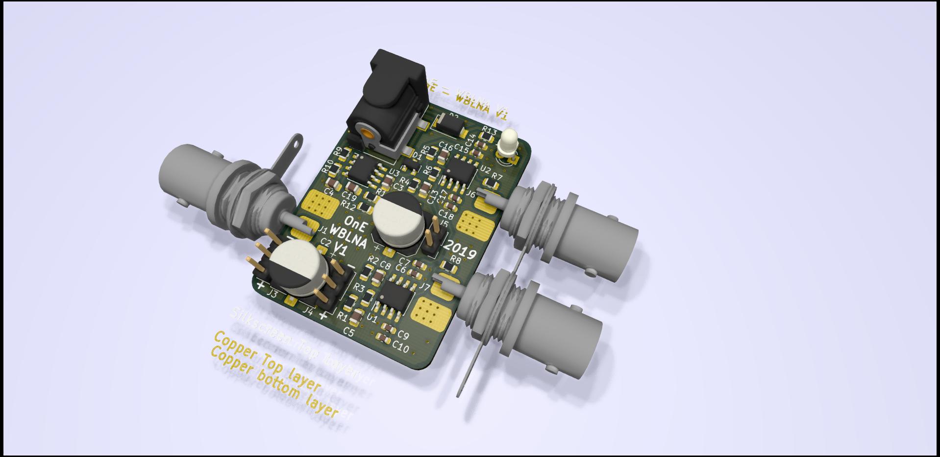
PCB Kicad 3D view :
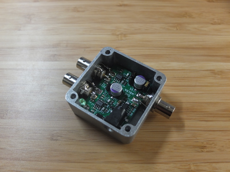
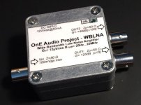
Picture of the finished prototype :
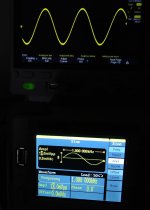
100ns pulse test input/output result :

So, i have published this projects as open source and it is available
to download on the GitHub repository here : \OnEAudioProjects\WBLNA
The project has been designed with Kicad 5.0.2
All original design files are available :
So i hope that will interest some people. 🙂
(Note that i have few bare PCB's available(4) , anyone interested can get one
with the panel stickers for 6€ worldwide shipping included )
Regards.
Frex
I designed some weeks ago a small tool to improve my noise instrumentation setup.
In fact, when doing wide-band noise measurement (well beyond what we can simply do with a sound card),
is is more difficult to measure low noise level.
One way is to use RMS measurement with an oscilloscope, but scope sensitivity doesn't go much less than a mV...
My latest AAPSU01 low noise PSU design is an example that can achieve low wide-band noise,
and so building this small tool has been motivate first by that.
So in practical manner, it's a small shielded box that include a low noise, high bandwidth and high gain amplifier.
The design specs are :
- 20Hz to 20MHz measurement bandwidth (-3 dB)
- 4th order Butterworth low pass filtering.
- Individual +20 dB(x10) and +40 dB(x100) outputs BNC
- 12 Vdc@50mA input supply.
- Max input amplitude about 100mVpp (with 12V supply)
- Output noise floor RTI ~ 12µVrms (Equal to En= 2.7nV/VHz)
- Can handle +/- 20VDC input offset voltage (AC coupled)
- Zin= 50 Ohms, AC or DC coupled (internal jumpers)
- Fully shielded design.
- Low cost design (full bom <30€ + PCB)
The design is based on LT6200-10 OPAMP from LinearTech (now AD).
It's a very high speed amplifier with 1.6GHz of GBW product
and less than 1nV/VHz of spectral noise density.
The full schematics is here : WBLNA_schematics
You can show below some picture of my unit and some measurements results.
PCB Kicad 3D view :
Picture of the finished prototype :
100ns pulse test input/output result :
So, i have published this projects as open source and it is available
to download on the GitHub repository here : \OnEAudioProjects\WBLNA
The project has been designed with Kicad 5.0.2
All original design files are available :
- Schematics
- Bill of material (with Mouser order codes)
- Mechanical drawing
- LTspice design files
- Gerbers files
- Panels stickers print
So i hope that will interest some people. 🙂
(Note that i have few bare PCB's available(4) , anyone interested can get one
with the panel stickers for 6€ worldwide shipping included )
Regards.
Frex
Frex, you keep surprising us!
Do you have an idea of the distortion of this amplifier up to say 50kHz?
Jan
Do you have an idea of the distortion of this amplifier up to say 50kHz?
Jan
Hello,
I don't have done THD measurement on it, but LT6200-10 datasheet specs show very good THD figure
up to MHz range.I'll try to make some measurements if i found time.
Regards.
Frex
I don't have done THD measurement on it, but LT6200-10 datasheet specs show very good THD figure
up to MHz range.I'll try to make some measurements if i found time.
Regards.
Frex
The LT6200 1/f knee is around 1kHz, not unusual for a high speed amp, but not ideal for audio work perhaps?
Do you have a measured noise-floor plot?
Do you have a measured noise-floor plot?
Hello,
It's not directly intended to audio stuff, but it can.
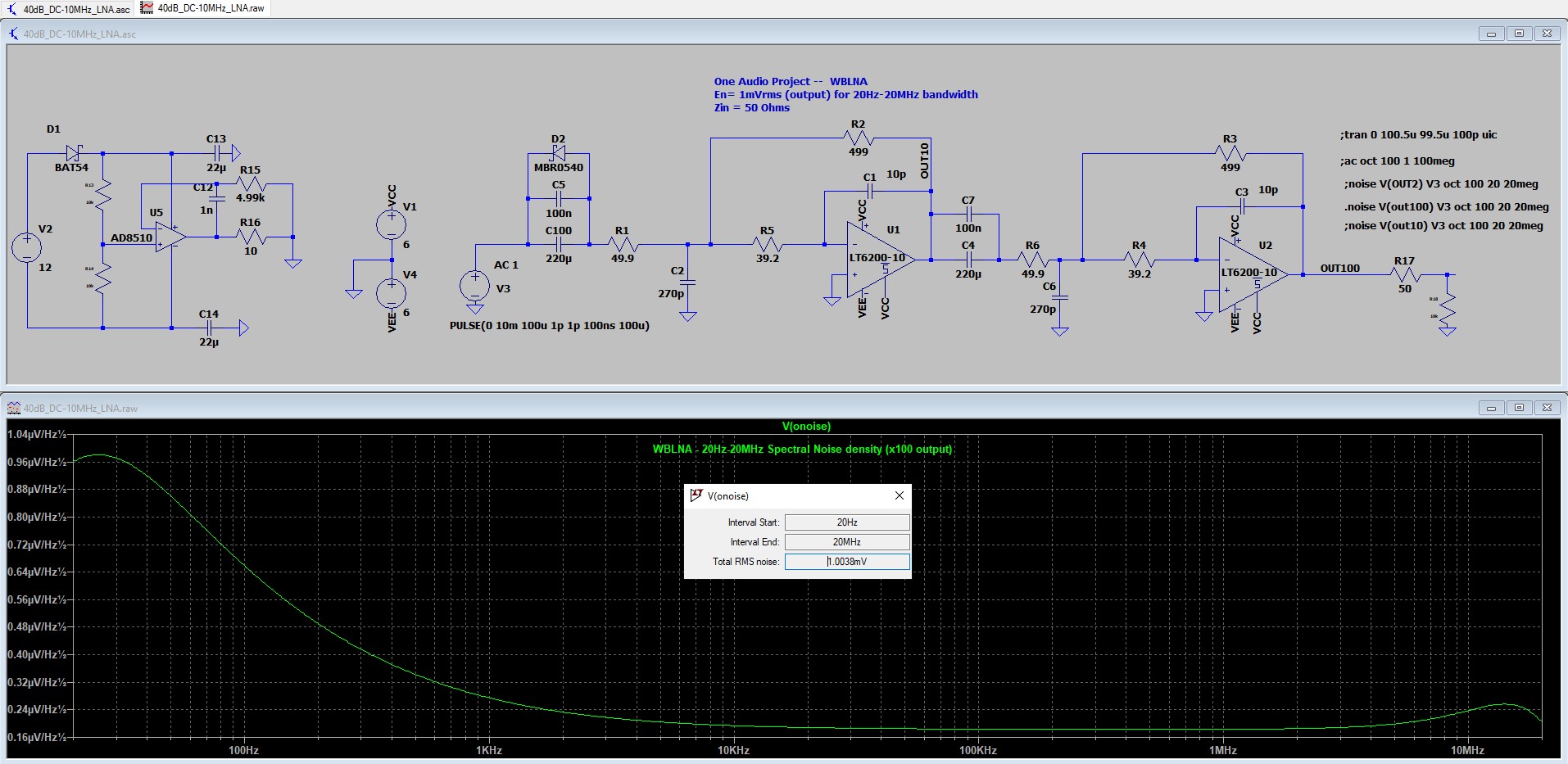
You can show on simulation of my design in LTSpice below
the noise spectra density between all bandwidth of 20Hz-20MHz.
It show an rms value of about 1mV, very near i had really measured on my prototype (1.2mV).
If you would take only audio bandwidth of 20Hz-20kHz, that would gave 31 µVrms that is 310nVrms RTI.
Regards.
Frex
It's not directly intended to audio stuff, but it can.
You can show on simulation of my design in LTSpice below
the noise spectra density between all bandwidth of 20Hz-20MHz.
It show an rms value of about 1mV, very near i had really measured on my prototype (1.2mV).
If you would take only audio bandwidth of 20Hz-20kHz, that would gave 31 µVrms that is 310nVrms RTI.
Regards.
Frex
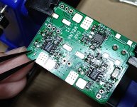
Just wanted to tell I built this amplifier by Frex (thanks again!).
Some small modifications were done. To make it capable of withstanding DC input voltages up to 30V, capacitors C1 is 50V and C2 35V. In addition there are also two anti-parallel 1N4148 diodes (one in each direction) after R1 to GND. Output connectors are isolated from chassis to minimize risk for ground loops.
So far it seems to work fine.
I'm not too fond about BNC connectors in such a small box, though. They will easily begin to rotate (if you don't make correct holes with squared sides). But then you don't have to lock cables, just pushing them onto the connectors is enough.
If one would like to make as perfect as possible chassis for a noise amplifier, take a look at Linear Application Note 159. Inner box Mu metal, middle copper and outer steel cookie tin! 😀
Attachments
Having a look at the circuit I'm perplexed by the topology - inverting stage is going to have a gain dependent on the source impedance, and there's a 50 ohm resistor and 39 ohm resistor in series with the input, responsible for pushing the noise density up above the amp's baseline.
Wouldn't a standard non-inverting config with smaller feedback resistors be more perfomant, say 220 / 22 ohm feedback resistors for x11 gain and only 0.6nV/√Hz to contribute.
Having a switchable 50/600/10k load resistor would be good too.
Wouldn't a standard non-inverting config with smaller feedback resistors be more perfomant, say 220 / 22 ohm feedback resistors for x11 gain and only 0.6nV/√Hz to contribute.
Having a switchable 50/600/10k load resistor would be good too.
Interesting. I could at least test if it is dependent on source impedance. Don't have equipment to test for noise level. Hopefully Frex can comment.
Edit. I can't really trust the equipment I have too much. The level of measurements I make I'm probably not going to see any difference.
Edit. I can't really trust the equipment I have too much. The level of measurements I make I'm probably not going to see any difference.
Last edited:
- Home
- Design & Build
- Equipment & Tools
- WBLNA - Wide Bandwidth low noise amplifier