Waynes BA2018 and Biamp 6-24 crossover
Just having purchased both of these I have the following questions.
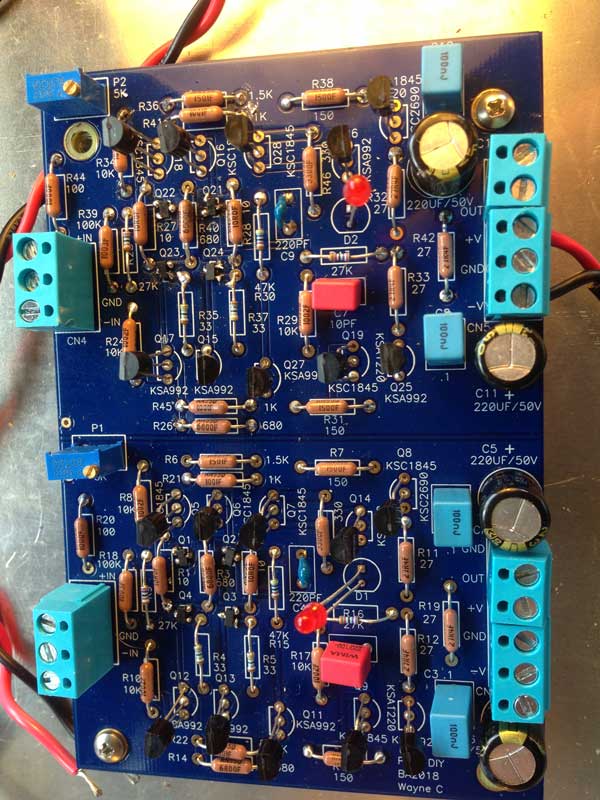
With Waynes BA2018 as a preamp I seem to have made a mess of the surface mounted Jfets. They are out of stock at Mouser and Digikey. Does DIY have a stock so I can attempt to replace them or am I relegated to getting the whole kit to try again? I purchased a new soldering iron for the job and I expect I will need to start again to get this happening. I propose gluing the little blighters with a small dab of contact before a careful soldering under magnification. Any help gratefully acknowledged.
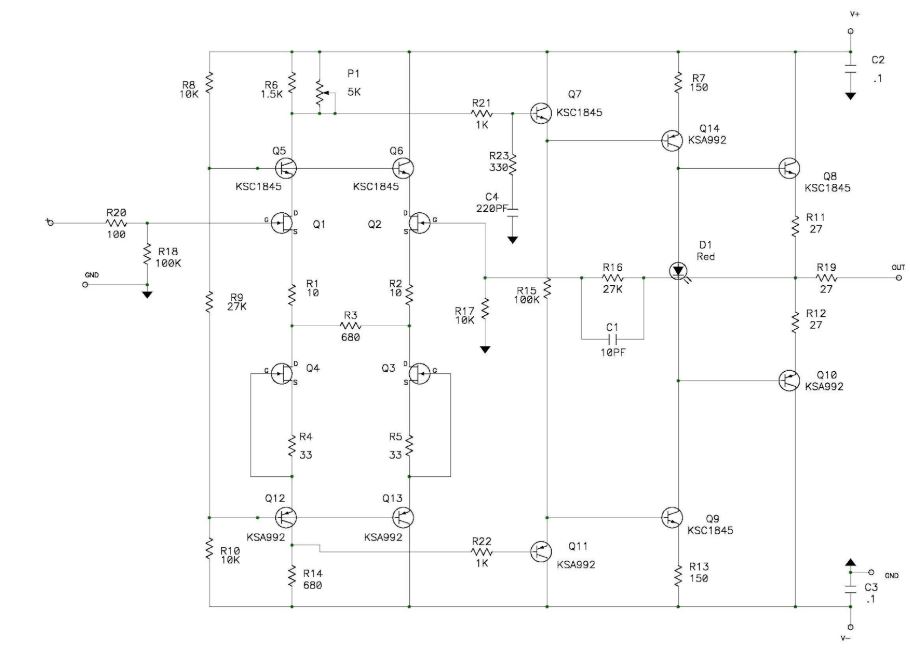
With the crossover I have read countless pages searching for the BOM. I know it must be somewhere but can't locate it . Do I have to just read the board? Nelson also said there was a build thread by 6L6. It's certainly not listed anywhere I can see.
I have also not been able to understand the way we work out what capacitor values are needed for a certain frequency. Sorry I am right down there before most of you ever heard the word electron. So I'm wanting to put frequencies up to 300Hertz through my transmission lines and everything else goes up. I can't understand the graphs that keep making everyone so happy. Just failed that intelligence test.
Maybe one of you kind boffins could help me to work this out using that lovely looking crossover board . Also those big side caps are a total mystery as to their value.
In my defense I built an Aleph J that has been flawless for a few years and am slowly getting the stuff together for a second one. My soldering is not attrocious and I can get things right with a small amount of assistance.
Cheers.
Dan
Just having purchased both of these I have the following questions.
With Waynes BA2018 as a preamp I seem to have made a mess of the surface mounted Jfets. They are out of stock at Mouser and Digikey. Does DIY have a stock so I can attempt to replace them or am I relegated to getting the whole kit to try again? I purchased a new soldering iron for the job and I expect I will need to start again to get this happening. I propose gluing the little blighters with a small dab of contact before a careful soldering under magnification. Any help gratefully acknowledged.
With the crossover I have read countless pages searching for the BOM. I know it must be somewhere but can't locate it . Do I have to just read the board? Nelson also said there was a build thread by 6L6. It's certainly not listed anywhere I can see.
I have also not been able to understand the way we work out what capacitor values are needed for a certain frequency. Sorry I am right down there before most of you ever heard the word electron. So I'm wanting to put frequencies up to 300Hertz through my transmission lines and everything else goes up. I can't understand the graphs that keep making everyone so happy. Just failed that intelligence test.
Maybe one of you kind boffins could help me to work this out using that lovely looking crossover board . Also those big side caps are a total mystery as to their value.
In my defense I built an Aleph J that has been flawless for a few years and am slowly getting the stuff together for a second one. My soldering is not attrocious and I can get things right with a small amount of assistance.
Cheers.
Dan
can you confirm voltages across R1 and R2?
no load, input shorted (if there is volume pot, pot on minimum)
regarding soldering JFets - soldering flux (helper liquid) is absolute must ( best are these sorta Calophone solutions, no cleaning afterwards)
prior to soldering put one blob of flux (tip of small screwdriver) in place of JFet
take JFet with tweezers, place and keep pressed with tweezers
clean solder tip, take small amount of solder on tip
bring to one JFet leg, solder in 1, 2, 3 sec - done
release tweezers, proceed soldering other 2 legs in usual way - bring solder wire to leg, lean it on tip, bring solder tip to wire, melt , flux will do it's job - what's melted it'll go where needed
again - flux is all difference - there is no capillary affect without it, at least not in reasonable time
plenty of tutorials on ootoobe
edit: give us pics, close, well lit, to inspect what you did
Last edited:
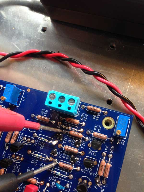
Hi Zen Mod, Thanks for your willingness to help.
I took some photos and voltage measurements today.
First with no power to the board
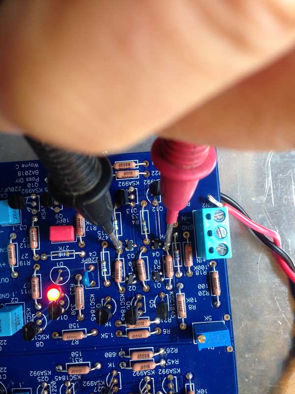
Second, this measured 0.12Volts
Third , This measured 5.6 volts
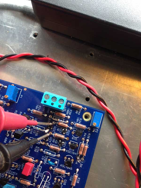
Fourth, this measured zero volts
Fifth, the board with power.
I took some photos and voltage measurements today.
First with no power to the board
Second, this measured 0.12Volts
Third , This measured 5.6 volts
Fourth, this measured zero volts
Fifth, the board with power.
So I reckon I completely failed to fit those surface mounted Jfets properly .
The question now is really whether I attempt to repair it or just start again from the beginning with the new information that you gave me about how to solder those tiny things.
Also still chasing a BOM for the crossover unit. Edit, found it, sorry.
The question now is really whether I attempt to repair it or just start again from the beginning with the new information that you gave me about how to solder those tiny things.
Also still chasing a BOM for the crossover unit. Edit, found it, sorry.
Last edited:
"across resistor" means - DMM set to voltage, one probe on one end of said resistor, second probe on second end of said resistor
do that for R1 and for R2
do that for R1 and for R2
R1 = .01V
R2 = .02V
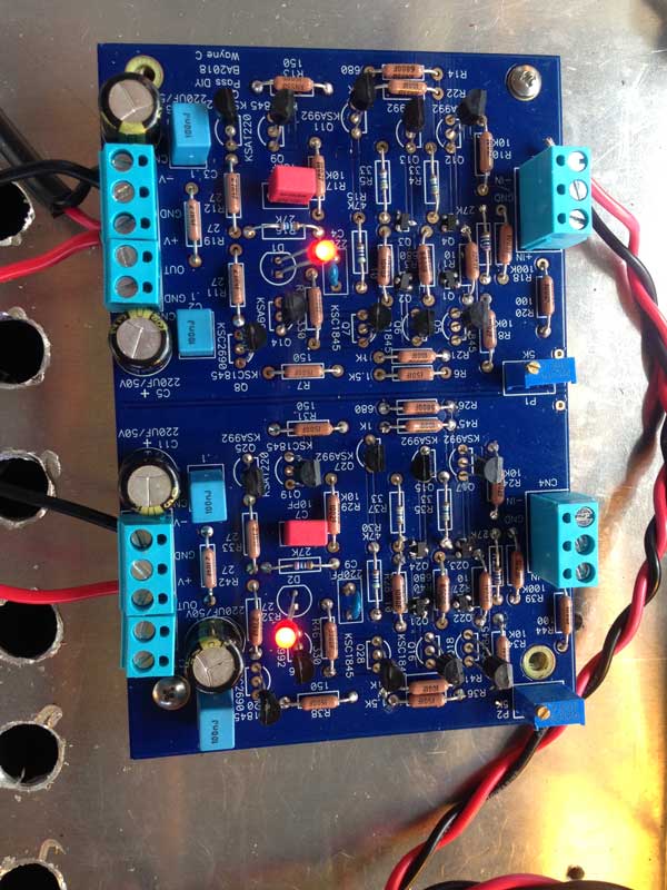
The output of this channel measures zero now between output and ground. Adjusting the trimpot brings it down quickly.
The other channel equivalent[sorry couldn't remember those R numbers.]
R1=0.2V
R2=0.3V
On this channel the output voltage is 8.3V and adjusting the trimpot makes no difference.
R2 = .02V
The output of this channel measures zero now between output and ground. Adjusting the trimpot brings it down quickly.
The other channel equivalent[sorry couldn't remember those R numbers.]
R1=0.2V
R2=0.3V
On this channel the output voltage is 8.3V and adjusting the trimpot makes no difference.
So what do you think Zen Mod? Should I start again from scratch or attempt to repair this?
But it seems those surface mount Jfets are out of stock everywhere except in a kit from DIY shop.
But it seems those surface mount Jfets are out of stock everywhere except in a kit from DIY shop.
at lower reading channel , current seems so - so ......... 1 and 2 mA
while on other channel currents computes as 20mA and 30mA ........ which is noooooo goood
so - best to find new JFets, and this time follow soldering procedure I explained
nothing is criticall as it seems, but mistakes are easy to make , then you have scorched part
while on other channel currents computes as 20mA and 30mA ........ which is noooooo goood
so - best to find new JFets, and this time follow soldering procedure I explained
nothing is criticall as it seems, but mistakes are easy to make , then you have scorched part
no damn equivalent 
just be patient and search
Digikey and Mouser aren't sole Vendors in world
for instance:
2SK209-BL(TE85L,F) TOSHIBA - Transistor: N-JFET | unipolar; 14mA; 150mW; SC59; Igt: 10mA; 2SK209 | TME - Electronic components
just be patient and search
Digikey and Mouser aren't sole Vendors in world
for instance:
2SK209-BL(TE85L,F) TOSHIBA - Transistor: N-JFET | unipolar; 14mA; 150mW; SC59; Igt: 10mA; 2SK209 | TME - Electronic components
I'm a lot later on this topic than others but... Did I just notice you have the 220 picofarad and the 10picofarad caps in the board swapped with each other? Or is it actually.. me, that swapped them? Cause the wima's say 220, and the ceramics say 100, which is 10 +0 zeroes. So, 1 0 - picofarad.Hi Zen Mod, Thanks for your willingness to help.
I took some photos and voltage measurements today.
First with no power to the board
Second, this measured 0.12Volts
Third , This measured 5.6 volts
Fourth, this measured zero volts
Fifth, the board with power.
Have you managed to fix it in mean time?
Oh and regarding those jfets (only now read the whole thread) I recommend getting a hot air station! They're actually quite cheap for a good one. And for keeping them in place while soldering with a hand iron: Use a chiseled cone - whatever it is. It's a pointy one but then the tip cut off at an angle on one side. And use blu-tack (blue tack?) to hold things down. It can melt, but it's easy enough to get off with IPA. I wouldn't glue them down because you risk not being able to solder, as well as them not sitting on completely. And it's a b**ch to get back off 😛
Speaking of dealing with this SMD stufff... I posted this awhile back: https://www.diyaudio.com/community/threads/waynes-ba-2018-linestage.329240/page-63#post-6241825
I am IPC-A-610 certified with alot of SMD experience. We are taught not to leave any residue or contamination on a pcb after assembly. If it CAN be cleaned, you clean it. Flux is fanstastic and necessary for the soldering process to go well, BUT... don't leave that crap on / under components. A few bouts and blasts of compressed air / isopropyl alcohol scrubbing is what you want. You don't want residue under your parts, unless you enjoy wiggly unwanted voltages and impedance, intermittent / no operation, long term failure, etc.
I am IPC-A-610 certified with alot of SMD experience. We are taught not to leave any residue or contamination on a pcb after assembly. If it CAN be cleaned, you clean it. Flux is fanstastic and necessary for the soldering process to go well, BUT... don't leave that crap on / under components. A few bouts and blasts of compressed air / isopropyl alcohol scrubbing is what you want. You don't want residue under your parts, unless you enjoy wiggly unwanted voltages and impedance, intermittent / no operation, long term failure, etc.
A couple of tips, check the connection from each leg to the next solder point on the trace for each JFET. You shouldn't have to struggle to get a reading. Also, get some isopropyl alcohol and clean all of the flux around the JFETs. You can try re flowing the solder points. Also, since these JFETs may be bad, you can use them to get some practice soldering and desoldering them.
The boards that DIYaudio supplies are of excellent quality. If you keep your soldering temperature low, you should have enough of opportunities to retry soldering the SMD. When you order them, get the 25 quantity. they are cheap. Also, if you decide to build another board etc in the future for balanced, dual mono, they should be matched close enough.
This is a great preamp and well worth the effort. I had 19v DC offset on one channel that I couldn't adjust. After inspecting, one leg had a bad connection. After reflowing the solder and cleaning, it sounds great with a very stable offset.
Best of luck!
to Wot:
for the parts list (BOM) of the 6-24 active crossover - you should read this:
https://www.firstwatt.com/pdf/art_diy biamp_6-24_ crossover.pdf
page 10
Cheers
Dirk
for the parts list (BOM) of the 6-24 active crossover - you should read this:
https://www.firstwatt.com/pdf/art_diy biamp_6-24_ crossover.pdf
page 10
Cheers
Dirk
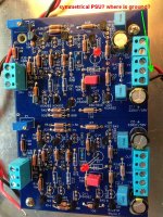
Good catch. That'd explain the partial functionHello Dan / Wot,
is that a symmetrical powersupply you are using? I don't see ground attached on the pics. Perhaps I missed it?
Cheers
Dirk
- Home
- Amplifiers
- Pass Labs
- Waynes BA2018 and Biamp 6-24 crossover, the basics.