Hi would would I add a Wattmeter to my amps simular to what McIntosh does in their amps? This way I would see the amount of power thats is being outputed.
Thanks
Ted
Thanks
Ted
Do you have a question to ask?
A while back (early 80's) I was toying around with using an analog multiplier to measure instantateous power. I monitored the voltage and, using a series resistor, the current. I fed these scaled inputs to the multiplier to generate the V*I product. I fed the output of the mulitplier to a DMM chip to display power. Worked pretty good, though I had to have a .1 Ohm resistor in series with the speaker.
I guess today you could use ADCs and a microcontroller.
Have fun.
get yourself an AD536
Analog has a series of true rms chips including the aforementioned -- if you are measuring power this is helpful since most dvm's don't measure rms acurately beyond a few kHz.
Hewlett Packard used the AD536 in their HP3478 and HP3468 dmm's.
Analog has a series of true rms chips including the aforementioned -- if you are measuring power this is helpful since most dvm's don't measure rms acurately beyond a few kHz.
Hewlett Packard used the AD536 in their HP3478 and HP3468 dmm's.
Sorry I mean I would like to add a wattmeter. Like this McIntosh unit
http://66.216.98.167/mcprod/products/McIntoshProduct.jsp?product_id=19
Just wondering if there are any good ways to implement it.
Thanks
Ted
http://66.216.98.167/mcprod/products/McIntoshProduct.jsp?product_id=19
Just wondering if there are any good ways to implement it.
Thanks
Ted
There are good ways to implement a power amplifier wattmeter to measure the power being fed to a speaker, but the only way to measure true power is for the meter to measure both output voltage and load current, multiply the two together, and display the resulting product in a meaningful way.
My approach was to display both peak power (using a peak detector circuit) and "average" power, using an integrator (low pass filter).
Many so-called power meters really only measure the voltage, meaning that the displayed power is only true for a real 8 Ohm load. At least back in the early 80's. loudspeakers had highly complex impedance curves and were 8 Ohms at maybe only one or two frequencies. So, while the voltage reading meters were useful, they were hardly accurate for measuring power.
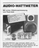
DIY TRMS Wattmeter
For those of You who want to DIY such a TrueRMS Wattmeter (average or peak reading; 20Hz to 20kHz; 100µW to 1kW) - Elektor 11/1993 had a very nice article/project about exactly this. It works with a DIY inductive current probe made from an empty solder tin coil which has almost zero negative effect on the signal
(no shunt resistor) . Truely a high-end meter but not exactly cheap because of two log-RMS Converter chips (SSM2110) and one ultra-low-noise Op-Amp. (LT1028).
Hi everybody:My approach was to display both peak power (using a peak detector circuit) and "average" power, using an integrator (low pass filter).
For those of You who want to DIY such a TrueRMS Wattmeter (average or peak reading; 20Hz to 20kHz; 100µW to 1kW) - Elektor 11/1993 had a very nice article/project about exactly this. It works with a DIY inductive current probe made from an empty solder tin coil which has almost zero negative effect on the signal
(no shunt resistor) . Truely a high-end meter but not exactly cheap because of two log-RMS Converter chips (SSM2110) and one ultra-low-noise Op-Amp. (LT1028).
Attachments
Intersting article - wish I had a copy.
I had considered a current probe rather than a series sense resistor, but I felt (wrongly perhaps) that it would cause worse problems. I mean, the current probe (which is wire wound around the output lead) forms a transformer, and I was unsure how this transformer would react with the amplifier and loudspeaker. In other words, I was unable to convince myself that a .1 Ohm non-inductive resistor would be audibly worse than an inductive current probe. Also, if there is any DC, a current probe watt meter would be insensitive to it. This could be good or bad, depending upon your point of view. To me, power is power and if I see 1 W of power when there is nothing coming out of the speakers, I know I have a major DC offset problem I need to investigate. With an ac coupled watt meter, I would never see this offset.
I think the log amp approach is pretty difficult to implement. I used some Analog Devices 4 quadrant multipliers which were easy to use. They were rather expensive, as I recall, but I was able to get samples through my work, where I also used them in several designs. I recall seeing some log amp designs to produce a mulitiplication function, but they look like a bare to get working properly.
Jeff:Intersting article - wish I had a copy.
If You don`t mind that the article is in German I scan it for You
(but at least the schematics and the PCB layout might be already helpful)
Just email me in case You like to have it (it may take a while ... but it comes).
Yes the current probe forms a transformer. In the article they specified the influence of the current transformer on the speaker cable (=primary winding of the current transformer) with an equivalent series-resistance of just 7mOhm (0.007 Ohms!). Compared to Your 0.1 Ohms series sensing resistor this is much better and I think the inductive influence is negligibly.
Well, DC cannot be sensed with this approuch of Wattmeter but also that`s another application IMO.
For investigating DC offset problems with an amp I think there is no need to measure current. Simple DCV measurement maybe completed with a comparator and some kind of simple display (LED) should do this.
The LT1028 is a GREAT chip. I've never used it for audio, but for instrumentation it's amazing.
Ironically, I'd turn the meters off if I were using the McIntosh.
Sheldon
Ironically, I'd turn the meters off if I were using the McIntosh.
Sheldon
watt is IxV
so you need to have a summing circuit
with a multiplying function
there are those ones
using special chips opamps
like CA3080
so you need to have a summing circuit
with a multiplying function
there are those ones
using special chips opamps
like CA3080
Re: sum to multiply
see also my homepage
or
my email
yesjackinnj said:you mean you need a "logarithmic circuit"
see also my homepage
or
my email
Meters on Mac and LT1028
Sometimes meters, if not isolated, can cause havoc with sound.
The LT1028 -- audio appears to be one of the things Linear had in mind,...
Sometimes meters, if not isolated, can cause havoc with sound.
The LT1028 -- audio appears to be one of the things Linear had in mind,...
isn't it 5:00 a.m. in Sweden?
well, I guess the sun never rises for the next couple weeks.
the AD536 has a logarithmic option, but you need to temperature compensate the output (yes, true of all analog amplifiers, but worse so when you are taking a log or exponentiating.) I have never been able to find a vendor for the thermistors they specify and was thinking to do it with an LM34 (is this the centigrade censor?, I forget), and an inverting opamp... there is an entire family of RMS chips from Analog.
By the way, Radio Shack has an excellent product called
KillaWatt, which plugs into your wall socket and you plug your
appliance, amplifier, what-have-you into it for power.
It tells you the AC voltage, current draw, power factor,
actual energy draw, and some other stuff.
It's pretty slick at a reasonable price.
😎
KillaWatt, which plugs into your wall socket and you plug your
appliance, amplifier, what-have-you into it for power.
It tells you the AC voltage, current draw, power factor,
actual energy draw, and some other stuff.
It's pretty slick at a reasonable price.
😎
Hall Effect Current Probe...
I picked up some sensors a while back, they are a linear hall effect current sensor. Basically the produce a output voltage in proportion to the current flowing through the center of the torroid, same as a current transformer, except they work at DC. Basically they're a hall sensor, inserted into a slit in a cut torroid.
They're a Microswitch/Honeywell CSLA2CD. They range to 100Amps, but can be converted to a smaller range by adding more turns around the torroid!
Might be a good way to measure the current... ...add an analog multiplier and you have a Wattmeter! (I use the current sensor, voltage probe, and multiply function on my scope to look at power waveforms)
-Dan
- Status
- Not open for further replies.
- Home
- Amplifiers
- Solid State
- Wattmeter