just curious after reading this thread...
http://www.diyaudio.com/forums/showthread/t-112471.html
I am unclear of the how many watts this amp puts out. I am calculating about 60watts. I have been known to be bad at this amp calculation stuff, so I figured I'd ask.
http://www.diyaudio.com/forums/showthread/t-112471.html
I am unclear of the how many watts this amp puts out. I am calculating about 60watts. I have been known to be bad at this amp calculation stuff, so I figured I'd ask.
Attachments
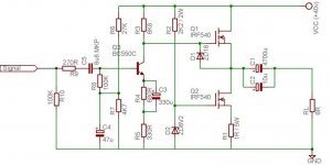
40 Volt - 5 V (mosfet gs) = 35 Volt total
35/2 = +- 17.5 Vpeak
17.5/1.414 = 12.4 Volt rms max ouput
Max 8 Ohm:
12.4 x 12.4 / 8 = 19.2 Watt RMS
Max 4 Ohm:
12.4 x 12.4 / 4 = 38.4 Watt RMS
Something like that for a 40 Volt DC supply.
The output, between MOSFETS, should be ajusted to something like 15 - 17 Volt.
Either for symmetrical clipping or minimum distortion at higher levels.

The irf540 being a 88w device in a to220 case may not be
up to the task of handeling all that heat!
up to the task of handeling all that heat!
lineup excuse my ignorance but
This calculation is made in each MOSFET = 2.5 v total of the two 5v.
you would use bipolar transistor 0.6 +0.6 v I correct?
This calculation is made in each MOSFET = 2.5 v total of the two 5v.
you would use bipolar transistor 0.6 +0.6 v I correct?
Even without output losses this voltage gives a max power of 24W at 8 ohm. Switching to bipolar won't buy you much additional power.
Hello Beto.
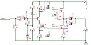
See attachment.
Actually I forgot that 2V is used by lower MOS. Like 2 A ClassA bias.
While like 5V, VGS, is lost in upper.
So totally we have 40 -2 -5 = 33 Volt (at best for output swing)
Same as +- 16.5 swing.
At idle, output voltage is at 18.5 VDC.
Output can not go lower than 2V .. because of MOS Current source.
Output can not go higher than 35V, because there Gate of MOSFET is at 40 VDC (supply max).
Result output +-16.5Vpeak = 11.66Vrms
Power 8 ohm : 11.66x11.66 /8 = 17 Wrms
Power 4 ohm : 11.66x11.66 /4 = 34 Wrms
These are teoretical max. In reality will be some losses and less power out.
====================
This amplifier maybr benefits from BOOTSTRAP.
Split up R3 (6k8) into two 3k3.
Bootstrap with 47-100uF, from output to BETWEEN 3k3 resistor.
Regards 🙂
Attachments
wattage concuest may be ????
in my company i own about a 50 pro amps for PA rentals ....the smalest is like 350w per channel .......
still all day i listen to music coming from a nicelly made P3 from esp .....something like 40+40 watts ....
can't change that .... now i am an edict .....
in my company i own about a 50 pro amps for PA rentals ....the smalest is like 350w per channel .......
still all day i listen to music coming from a nicelly made P3 from esp .....something like 40+40 watts ....
can't change that .... now i am an edict .....
It seems to me that the bias is all wrong:
BJT base voltage is around 5V
BJT DC current is around 5mA
=> BJT collector voltage 10V
Now, how can you expect a decent voltage swing? Or am I missing something? I would decrease R3 to, say, 3k3 or something...
BJT base voltage is around 5V
BJT DC current is around 5mA
=> BJT collector voltage 10V
Now, how can you expect a decent voltage swing? Or am I missing something? I would decrease R3 to, say, 3k3 or something...
Yes, you are probably right.
Of course we should adjust the output voltage point.
This can be done by increasing R6 (27k). Could be replaced, temporary, with one 50-100 kohm trimpot.
My earlier post estimation of a good DC operation point for output,
would indicate something like 16-18.5 Volt.
A bit lower than 1/2 of supply voltage.
The Voltage Gain, Gv, is defined by R3/R5.
Which gives approximate ( 6k8/330 ) Gv = 20.
A bit lower gain than 20 can be expected..
this is a single ended amplifier with a constant current load.
If the bias (and CCS) is set to 2A then the maximum current swing from the amplifier is 2Apk.
Don't even think about using less than 8ohms speakers.
Even these will require much more than 2Apk on short term transients.
If the bias (and CCS) is set to 2A then the maximum current swing from the amplifier is 2Apk.
Don't even think about using less than 8ohms speakers.
Even these will require much more than 2Apk on short term transients.
True!
And as MOSFET will get hot (80 Watt idle)
it is questionable if IRF540 (TO-220) can make 40 Watt each.
IRF640 or even IRFP240 may be required ...?
And as MOSFET will get hot (80 Watt idle)
it is questionable if IRF540 (TO-220) can make 40 Watt each.
IRF640 or even IRFP240 may be required ...?
Hi,
SOAR of the 540 is not a problem.
You can run Tc<=100degC leaving an effective dissipation of 40W from the devices.
The problem is peak current on transients. This amp can only deliver 2A and will current clip.
A heatsink of about 0.6C/W to 0.7C/W for 40V & 2A will work at these very high temperatures. The amp can deliver about 15W to 16W into 8r0 but it cannot deliver into a reactive 8ohms.
However, it could make an excellent 9W into 16ohm amplifier.
or
reduce the voltage to 30V and increase the bias to 3.5A on a 0.3C/W sink for 8W into 8ohms speakers
I would be tempted to run with a pair of isolated heatsinks, with each FET direct coupled to it's sink.
Okay, so the IRF540 may do it. This is good.
IRF540N variant is even better for higher heat.
When I design Class A, I use some 'normal worst case' numbers to calculate for current.
If make class A for 8 Ohm .. I use Bias Current for 5 Ohm (+ 10% extra)
for nominal output power level.
Same way, for 4 Ohms speakers, it is better to use like 2.5 - 3 Ohm value
for the calculations.
Yes, using like 30 VDC and 2.5-3.0 Ampere may be a first best try.
- Status
- Not open for further replies.
- Home
- Amplifiers
- Solid State
- wattage question