After reading up on the lamps, I began to have 2nd thoughts about the big 11.5" metal halide lamps with 4k color temp I was going for ($160AU).
I searched around a bit more and ended up going with the kit here 🙂:
https://secure.lumenlab.com/shop/group.php?id=4 (the 230V version ofcourse 🙂 )
Cost me over $100 more (post was $60AU) but look at these specs 😀
* 33,000 lumens (great)
* 5200K color temp (bit on the high side, but should be good)
* 85 CRI (danm how nice is this, kicks the CRI of 65 on the others)
* 27mm arc gap
* ANSI S51
* 20,000 hour life (Couldnt ask for much more, and this is for projectors so should last the distance)
I didnt spend as much as i thought on the monitor and OHP, so this allowed me to spend the extra on the lighting 😀.
What do u guys think 🙂?
I am getting that exact bulb (not from lumenlab) and an HPS magnetic ballast. I posted a thread about these in the lighting section:
http://www.diyaudio.com/forums/showthread.php?s=&threadid=65296
I haven't gotten to test it out yet because I need a socket for the bulb. But, they look to be in good condition. 🙂 Good choice for the bulb I would say.
http://www.diyaudio.com/forums/showthread.php?s=&threadid=65296
I haven't gotten to test it out yet because I need a socket for the bulb. But, they look to be in good condition. 🙂 Good choice for the bulb I would say.
Cool 🙂
Ill keep my eye on that thread 🙂
only think I am worried about is that I didnt order a UV/IR filter as i forgot about it. Is this important for an OHP setup?
Ill keep my eye on that thread 🙂
only think I am worried about is that I didnt order a UV/IR filter as i forgot about it. Is this important for an OHP setup?
im gona look into seeing if i cant get some of this: http://www.solargard.com.au/2.0/index.php?page=sterling and apply it to the bottom side of the Glass Stage.
that would be great
We have a similar product in the US, but it is difficult to buy. (They limit sales to trained installers.) The selective film I have tried passed about 81% of the visible light, but did a pretty good job of blocking the IR. Not as good as hot mirror, but much cheaper.
If you can get a free 1 foot square sample, that might be all you need! Maybe tell them you are thinking about getting all your house windows done, but want to run some tests first. 😀
well I have got my OHP and the lamp + ballast
I have mounted the lamp +socket to the side of the OHP (bit shoddy but its mounted), and the Ballast is mounted to the outside of the OHP.
When I power it up however, it lights up the whole room lol. With the old halogen lamps in side it didnt do this and gave a nice clear sharp screen on the wall. I made a temp enclosure for it out of a box (lol) so as to block out stray light and keep the room darkish, however the projection on the wall is not bright, with shadows in some areas.
Any idea why this is? do i need a new fiscial lense for the new 400W metal halide lamp (which also has the light producing part of the lamp a little to one side).
Im wondering how im gona get a reflector for such a lamp also :S:S, and if anything shiny will do (eg some aluminium curved).
My LCD should arrive next week so ill see how that goes, but with the current light projection, im a little worried about the brightness.
replacement lamp
There is one exact position for the center of the lamp arc: It has to go right where the old lamp's filament was. That is the point that will light the whole stage surface with a cone of rays that converge into the projection lens.
If the lamp arc is off to one side, then most of the light will miss the lens. If it is a bit too high or low, then the fresnels will focus the arc image in front of or past the projection lens. Try adjusting the lamp arc position until you get all the light going into the lens. You can see where it is going by removing the lens assembly, and moving a piece of white paper around above the stage. The best spot will be right at the center of the lens, midway through the lens assembly. In most OHPs, that is right where the mirror goes. If you have a triplet before or after the mirror, then the best focal point will be in the middle of the triplet.
You might want to see if you can find an Ikea napkin holder to use as a reflector. They are very spherical and highly polished aluminum. I use a silver-plated pastry mold that has a perfect half-sphere shape, with my Ushio lamp.
hmm, the height i can prob get right as the projection lens can be adjusted, however with it being to far to one side, thats an issue 🙁. the lamp arc (the part of the lamp that produces the light?) is about 6.75" from the start of the base, however the lamp acr needs to start 5.75" from the side of the enclosure (so it is 1inch to far to one side). I cant see any way of positioning the lamp acr 5.75" from one side unless I cut a hole in the side of the projector and have the base sticking out by 1 inch, however even if i do this, I dont know how I would support the base with nothing to screw into.
Hmm maybe I can bend a rectangluar sheet of metal like this:
and mount it outside with the base for the bulb screwed into it and going throuhg a hole in the side of the OHP. What do you think?
Thanks for ur reply man, really appreciate ur advice/help with all of this.
Ill try and find one of those ikea napkin holders, to buy or at least to gain an understanding of the sort of thing i need to aquire 🙂
Ill try to lay my hands on a digital camera and take some pics later.
Hmm maybe I can bend a rectangluar sheet of metal like this:
An externally hosted image should be here but it was not working when we last tested it.
and mount it outside with the base for the bulb screwed into it and going throuhg a hole in the side of the OHP. What do you think?
Thanks for ur reply man, really appreciate ur advice/help with all of this.
Ill try and find one of those ikea napkin holders, to buy or at least to gain an understanding of the sort of thing i need to aquire 🙂
Ill try to lay my hands on a digital camera and take some pics later.
adjusting the height
You can't just compensate for the lamp position by adjusting the distance between the LCD and the projection lens. That distance is a product of the throw distance and the lens focal length.
Your task is to adjust the distance between the lamp arc and the fresnels, so the projected image of the lamp arc ends up in the very center of the projection lens when the projector is focussed to give you an LCD image at the correct throw distance. It does you no good to fix the lamp arc at a particular LCD to lens distance, and then to change that distance to focus on your screen. You really have to work backwards.
But that is not difficult if you have an adjustable lamp position: You put the projector where you want it to sit. Focus an image on the screen using the LCD to lens distance adjustment. Then use the lamp height adjustment to get the best bright and even image on the screen.
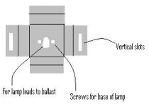
I think your recessed mounting box idea will work fine. You should make it easily adjustable up/down, by using vertical slots in the box flanges with screws that go through the slots into the original OHP side wall. Then you will be able to use different throw distances for different occasions.
You can't just compensate for the lamp position by adjusting the distance between the LCD and the projection lens. That distance is a product of the throw distance and the lens focal length.
Your task is to adjust the distance between the lamp arc and the fresnels, so the projected image of the lamp arc ends up in the very center of the projection lens when the projector is focussed to give you an LCD image at the correct throw distance. It does you no good to fix the lamp arc at a particular LCD to lens distance, and then to change that distance to focus on your screen. You really have to work backwards.
But that is not difficult if you have an adjustable lamp position: You put the projector where you want it to sit. Focus an image on the screen using the LCD to lens distance adjustment. Then use the lamp height adjustment to get the best bright and even image on the screen.
I think your recessed mounting box idea will work fine. You should make it easily adjustable up/down, by using vertical slots in the box flanges with screws that go through the slots into the original OHP side wall. Then you will be able to use different throw distances for different occasions.

ahhh i see, ok ill set the projection lense in place 1st then.
sweet idea making the lamp height adjustable!!
Im not sure how i will make vertical slots but im sure ill figure it out 😀.
Is this correct 🙂?:
sweet idea making the lamp height adjustable!!
Im not sure how i will make vertical slots but im sure ill figure it out 😀.
Is this correct 🙂?:
An externally hosted image should be here but it was not working when we last tested it.

great.
ahh, i was thinking about making the fabricated part 2x longer (in height) than the hole in the projector, but ur right, flanges on the top and bottom would be a better idea.
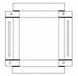
cheers for the diagram. shame i cant buy anything already molded like that 😛. To make itim gona get a square foot sheet of metal (thin) and cut the corners out then bend it like shown:
ahh, i was thinking about making the fabricated part 2x longer (in height) than the hole in the projector, but ur right, flanges on the top and bottom would be a better idea.
cheers for the diagram. shame i cant buy anything already molded like that 😛. To make itim gona get a square foot sheet of metal (thin) and cut the corners out then bend it like shown:
Attachments
or include some tabs
You could include some tabs (A, B, C, & D) to fold around the corners. Glue or screw them to make a sturdy box.
Also, I would make the slots long enough so you could use two screws in each slot. They would maintain the correct centering by preventing rotation.
Cuts are heavy lines, bends are broken lines:
Attachments
sounds good 😀 ill glue them unless i can borrow a soldering iron 🙂. another nice idea 🙂, if I have enough room ill be sure to make 2 screw holes 🙂
feeling much more confident about continueing now 😀, will check the local hardware store tomorrow to see if i can find a nice 1sqr foot of thin metal 🙂.
feeling much more confident about continueing now 😀, will check the local hardware store tomorrow to see if i can find a nice 1sqr foot of thin metal 🙂.
- Status
- Not open for further replies.
- Home
- General Interest
- Everything Else
- The Moving Image
- DIY Projectors
- Wanting to Make my Own DIY Projection Setup but need a little help